ESP32ADC驱动摇杆模块(基于IDF)
ESP32有两个12为位的SARADC,支持18个模拟通道输入由官方手册文档可知,ESP32的ADC电压输入只支持最高2450mv,当电压高于此值时测量的误差就相对较大了,并且支持的电压输入与Attend的设置也有关。
一.ESP32ADC资源介绍
ESP32有两个12为位的SAR ADC,支持18个模拟通道输入
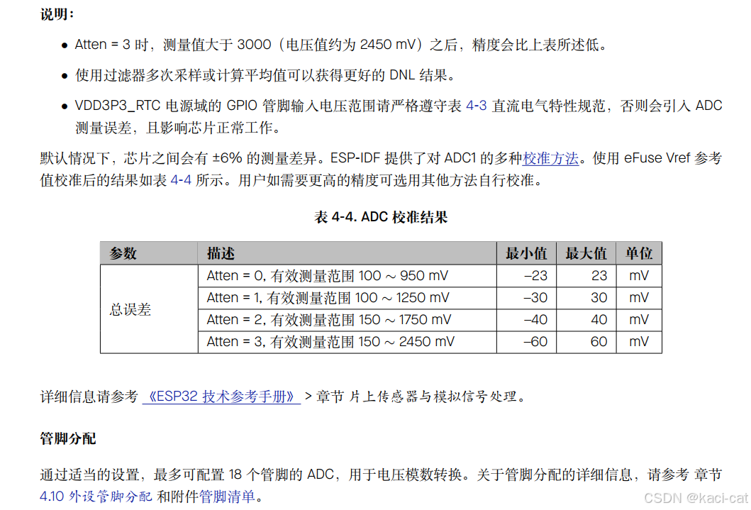
由官方手册文档可知,ESP32的ADC电压输入只支持最高2450mv,当电压高于此值时测量的误差就相对较大了,并且支持的电压输入与Attend的设置也有关。
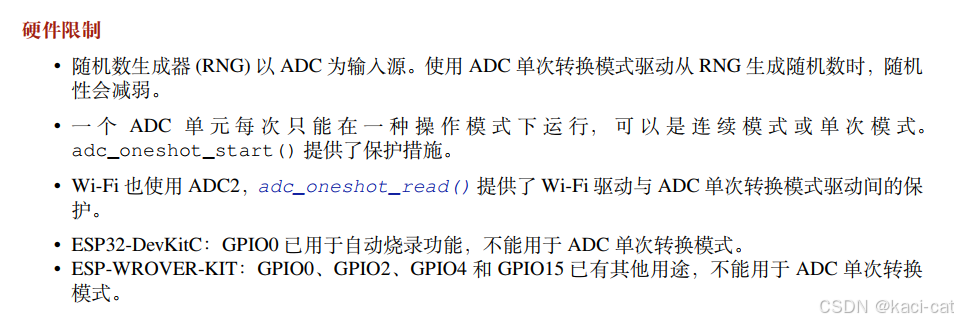
硬件限制:
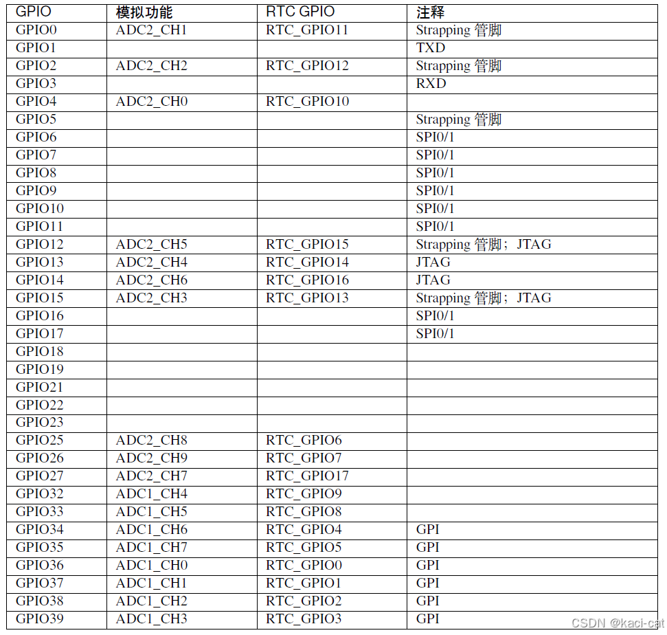
输入IO口
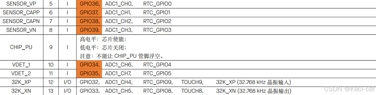
VP是GPIO36,VN是GPIO39,37和38在开发板上没找到
由于WIFI使用到了ADC2,考虑到WIFI是这个芯片的特色功能,所以只使用ADC1就可以了,能找到的IO口有GPIO32,GPIO33,GPIO34,GPIO35,GPIO36,GPIO39,可以优先使用橙色加深的,这些是只能用作输入且没有上下拉电阻的IO口.
二.代码部分
由于ESP32模块的adc电压测量范围最大为2.4V,可用的电压是3.3v,将3.3v电压用四个100欧姆的电阻串联,将摇杆模块5v接在3/4倍的3.3V电压处;
joystick.h
#ifndef __JOYSTICK_H__
#define __JOYSTICK_H__

#include "freertos/FreeRTOS.h"
#include "freertos/queue.h"

typedef struct {
    int x_voltage;
    int y_voltage;
} joystick_message_t ;

extern QueueHandle_t joystick_event_queue;

void joystick_Init(void);

void joystick_task_example(void *arg);

void joystick_task_create();

#endif
joystick.c
#include <stdio.h>
#include <stdlib.h>
#include <string.h>
#include "freertos/FreeRTOS.h"
#include "freertos/task.h"
#include "freertos/queue.h"
#include "soc/soc_caps.h"
#include "esp_log.h"
#include "esp_adc/adc_oneshot.h"
#include "esp_adc/adc_cali.h"
#include "esp_adc/adc_cali_scheme.h"


const static char *TAG = "EXAMPLE";

#define EXAMPLE_ADC1_CHAN0          ADC_CHANNEL_4
#define EXAMPLE_ADC1_CHAN1          ADC_CHANNEL_5

#define EXAMPLE_ADC_ATTEN           ADC_ATTEN_DB_12

typedef struct {
    int x_voltage;
    int y_voltage;
} joystick_message_t ;

static int adc_raw[2][10];
static int voltage[2][10];

QueueHandle_t joystick_event_queue;

adc_oneshot_unit_handle_t adc1_handle;

bool do_calibration1_chan0 ;
bool do_calibration1_chan1 ;

adc_cali_handle_t adc1_cali_chan0_handle =NULL;
adc_cali_handle_t adc1_cali_chan1_handle =NULL;


static bool example_adc_calibration_init(adc_unit_t unit, adc_channel_t channel, adc_atten_t atten, adc_cali_handle_t *out_handle);
static void example_adc_calibration_deinit(adc_cali_handle_t handle);

void joystick_Init(void)
{
    adc_oneshot_unit_init_cfg_t init_config1 = {
        .unit_id = ADC_UNIT_1,
    };
    ESP_ERROR_CHECK(adc_oneshot_new_unit(&init_config1, &adc1_handle));
    adc_oneshot_chan_cfg_t config = {
        .bitwidth =ADC_BITWIDTH_DEFAULT,
        .atten = EXAMPLE_ADC_ATTEN,
    };
    ESP_ERROR_CHECK(adc_oneshot_config_channel(adc1_handle, EXAMPLE_ADC1_CHAN0, &config));
    ESP_ERROR_CHECK(adc_oneshot_config_channel(adc1_handle, EXAMPLE_ADC1_CHAN1, &config));
    do_calibration1_chan0 = example_adc_calibration_init(ADC_UNIT_1, EXAMPLE_ADC1_CHAN0, EXAMPLE_ADC_ATTEN, &adc1_cali_chan0_handle);
    do_calibration1_chan1 = example_adc_calibration_init(ADC_UNIT_1, EXAMPLE_ADC1_CHAN1, EXAMPLE_ADC_ATTEN, &adc1_cali_chan1_handle);
    printf("----------------------%d\n",do_calibration1_chan0);
    printf("----------------------%d\n",do_calibration1_chan1);

    joystick_event_queue = xQueueCreate(10, sizeof(joystick_message_t));
}
void joystick_task_example(void *arg)
{
    joystick_message_t jmsg;
    while (1)
    {
        ESP_ERROR_CHECK(adc_oneshot_read(adc1_handle, EXAMPLE_ADC1_CHAN0, &adc_raw[0][0]));
        ESP_LOGI(TAG, "ADC%d Channel[%d] Raw Data: %d", ADC_UNIT_1 + 1, EXAMPLE_ADC1_CHAN0, adc_raw[0][0]);
        if (do_calibration1_chan0) {
            ESP_ERROR_CHECK(adc_cali_raw_to_voltage(adc1_cali_chan0_handle, adc_raw[0][0],  &voltage[0][0]));
            jmsg.x_voltage=voltage[0][0];
            ESP_LOGI(TAG, "ADC%d Channel[%d] Cali Voltage: %d mV", ADC_UNIT_1 + 1, EXAMPLE_ADC1_CHAN0, voltage[0][0]);
        }
        vTaskDelay(pdMS_TO_TICKS(1000));

        ESP_ERROR_CHECK(adc_oneshot_read(adc1_handle, EXAMPLE_ADC1_CHAN1, &adc_raw[0][1]));
        ESP_LOGI(TAG, "ADC%d Channel[%d] Raw Data: %d", ADC_UNIT_1 + 1, EXAMPLE_ADC1_CHAN1, adc_raw[0][1]);
        printf("%d\n",do_calibration1_chan1);
        if (do_calibration1_chan1) {
            ESP_ERROR_CHECK(adc_cali_raw_to_voltage(adc1_cali_chan1_handle, adc_raw[0][1], &voltage[0][1]));
            jmsg.y_voltage=voltage[0][1];
            ESP_LOGI(TAG, "ADC%d Channel[%d] Cali Voltage: %d mV", ADC_UNIT_1 + 1, EXAMPLE_ADC1_CHAN1, voltage[0][1]);
            xQueueSend(joystick_event_queue, &jmsg, portMAX_DELAY);
        }
        vTaskDelay(pdMS_TO_TICKS(1000));

        // Tear Down
        // ESP_ERROR_CHECK(adc_oneshot_del_unit(adc1_handle));
        // if (do_calibration1_chan0) {
        //     example_adc_calibration_deinit(adc1_cali_chan0_handle);
        // }
        // if (do_calibration1_chan1) {
        //     example_adc_calibration_deinit(adc1_cali_chan1_handle);
        // }

        // vTaskDelete(NULL);
    }
}

static bool example_adc_calibration_init(adc_unit_t unit, adc_channel_t channel, adc_atten_t atten, adc_cali_handle_t *out_handle)
{
    adc_cali_handle_t handle = NULL;
    esp_err_t ret = ESP_FAIL;
    bool calibrated = false;

#if ADC_CALI_SCHEME_CURVE_FITTING_SUPPORTED
    if (!calibrated) {
        ESP_LOGI(TAG, "calibration scheme version is %s", "Curve Fitting");
        adc_cali_curve_fitting_config_t cali_config = {
            .unit_id = unit,
            .chan = channel,
            .atten = atten,
            .bitwidth = ADC_BITWIDTH_DEFAULT,
        };
        ret = adc_cali_create_scheme_curve_fitting(&cali_config, &handle);
        if (ret == ESP_OK) {
            calibrated = true;
        }
    }
#endif

#if ADC_CALI_SCHEME_LINE_FITTING_SUPPORTED
    if (!calibrated) {
        ESP_LOGI(TAG, "calibration scheme version is %s", "Line Fitting");
        adc_cali_line_fitting_config_t cali_config = {
            .unit_id = unit,
            .atten = atten,
            .bitwidth = ADC_BITWIDTH_DEFAULT,
        };
        ret = adc_cali_create_scheme_line_fitting(&cali_config, &handle);
        if (ret == ESP_OK) {
            calibrated = true;
        }
    }
#endif

    *out_handle = handle;
    if (ret == ESP_OK) {
        ESP_LOGI(TAG, "Calibration Success");
    } else if (ret == ESP_ERR_NOT_SUPPORTED || !calibrated) {
        ESP_LOGW(TAG, "eFuse not burnt, skip software calibration");
    } else {
        ESP_LOGE(TAG, "Invalid arg or no memory");
    }

    return calibrated;
}

static void example_adc_calibration_deinit(adc_cali_handle_t handle)
{
#if ADC_CALI_SCHEME_CURVE_FITTING_SUPPORTED
    ESP_LOGI(TAG, "deregister %s calibration scheme", "Curve Fitting");
    ESP_ERROR_CHECK(adc_cali_delete_scheme_curve_fitting(handle));

#elif ADC_CALI_SCHEME_LINE_FITTING_SUPPORTED
    // ESP_LOGI(TAG, "deregister %s calibration scheme", "Line Fitting");
    ESP_ERROR_CHECK(adc_cali_delete_scheme_line_fitting(handle));
#endif
}

void joystick_task_create() {
    xTaskCreate(joystick_task_example, "joystick_task_example", 2048, NULL, 10, NULL);
}

// 使用示例

    // joystick_Init();
    // joystick_message_t jmsg;
    // joystick_task_create();
    // while(1)
    // {
    //     vTaskDelay(100);
    //     if(xQueueReceive(joystick_event_queue, &jmsg, portMAX_DELAY)){
    //         printf("x_voltage:%d\n",jmsg.x_voltage);
    //         printf("y_voltage:%d\n",jmsg.y_voltage);
    //     }
    // }
补充一个函数
函数功能:通过读取的joystickx轴和y轴的数据(值大概在140mv到2450mv之间,静置时两轴的输出量均为1225mv)返回两个数据表示小车左右两轮的数据(值在-100到100之间)可以通过函数将xy轴的读取到的摇杆数据转化为小车的左右轮子速度来控制小车运动状态
#include <stdio.h>
#include <math.h>

void voltage_to_speeds(int x, int y, int *left_speed, int *right_speed) {
    // 检查输入值是否在有效范围内
    if (x < 140 || x > 2450 || y < 140 || y > 2450) {
        printf("输入值必须在140到2450之间\n");
        return;
    }

    // 将x和y的值映射到-100到100的速度范围内
    float x_speed = (float)(x - 1225) / 11.05;
    float y_speed = (float)(y - 1225) / 11.05;

    //计算小车轮速的基准值;为x轴映射速度和y轴映射速度平方和开根号*0.6,0.6为系数可以自己根据实际运动状态调节
    float base_speed = 0.6*sqrt(pow(x_speed, 2) + pow(y_speed, 2));

    // 计算左右轮的速度差值,两轮的速度差值由x轴的输出量单独控制系数为0.3可以自己调节
    float speed_diff =0.3*x_speed ;

    // 计算左右轮的实际速度
    *left_speed = (int)(base_speed  - speed_diff);
    *right_speed = (int)(base_speed  + speed_diff);

    // 确保速度值在-100到100之间
    *left_speed = (*left_speed > 100) ? 100 : (*left_speed < -100) ? -100 : *left_speed;
    *right_speed = (*right_speed > 100) ? 100 : (*right_speed < -100) ? -100 : *right_speed;
    //此时输出的值始终大于0;当y<0时小车实际后退,速度值为负数(先将速度值与diff speed相加后再取反)
    if(y_speed<0)
    {
        *left_speed=-left_speed;
        *right_speed=-right_speed;


    }
}
注意:这个函数输出的速度的大小始终大于0需要维护
补充问题:(C语言位运算知识)
二进制存储
此函数返回两个int类型的值表示两个轮子的速度,值在-100到100之间
如果想把这两个速度值使用蓝牙模块传输给从机,由于传输的数据包的最小单位为uint8_t,(uint8_t可以表示0-255之间,-100到100之间一共201个数,所以一个轮子的速度可以用一个数据包的一个最小单位进行传输)所以传输前必须把int值强转换为uint8_t,但是强转之后在从机强转回来之后数据会改变,下面是值的变化情况
for(int i=-100;i<=100;i++){
		printf("%d----->",i);
		uint8_t j=(uint8_t)i;

		printf("%d----->",j);

		int k=(int )j;

//		if (k>=156)
//		{
//			k=k|(0xffffff00);
//		}


		printf("%d\n",k);
-100到-1之间的值会变为156到255
以-100为例
在计算机中,整数通常使用二进制补码(two's complement)形式表示。二进制补码是一种表示有符号整数的系统,它允许使用相同的位数来表示正数和负数。
对于int类型(假设是32位),-100的二进制补码表示如下:
-
首先,找到
100的二进制表示。由于100小于256(即2^8),它可以用一个字节(8位)来表示,但因为我们正在考虑int(32位),所以需要在前面填充24个0:00000000 00000000 00000000 01100100
这是
100的32位二进制表示。 -
接下来,取这个二进制数的反码(即每位取反,0变为1,1变为0):
11111111 11111111 11111111 10011011
-
最后,加1得到
-100的二进制补码表示:11111111 11111111 11111111 10011100
所以,-100在32位int类型中的二进制补码表示是11111111 11111111 11111111 10011100。
如果你在一个不同的位数系统(如16位int或64位int)中工作,步骤是相同的,但你需要调整填充的0的数量以匹配该系统的位数。然而,在现代计算机上,int通常指的是32位整数。
所以-100转换为uint8_t之后就是 10011100 就是156,转换为int类型就是00000000 00000000 00000000 10011100 。
位运算
在C语言中,位运算(Bitwise Operations)是一种直接对整数在内存中的二进制位进行操作的方法。这些操作包括位与(AND)、位或(OR)、位非(NOT)、位异或(XOR)、左移(Left Shift)和右移(Right Shift)。位运算在处理低级数据、优化性能、进行位掩码操作等方面非常有用。
以下是C语言中常见的位运算及其用法:
-
位与(Bitwise AND,
&):
对两个数的每一位执行逻辑与操作。如果两个相应的位都为1,则结果的该位为1;否则为0。int a = 5; // 二进制: 0101int b = 3; // 二进制: 0011int c = a & b; // 结果: 0001 (即1) -
位或(Bitwise OR,
|):
对两个数的每一位执行逻辑或操作。如果两个相应的位中至少有一个为1,则结果的该位为1;否则为0。int a = 5; // 二进制: 0101int b = 3; // 二进制: 0011int c = a | b; // 结果: 0111 (即7) -
位非(Bitwise NOT,
~):
对一个数的每一位执行逻辑非操作。如果某一位为1,则结果的该位为0;如果为0,则结果的该位为1。int a = 5; // 二进制: 0101int b = ~a; // 结果: 1010 (对于8位二进制表示,实际结果取决于整数类型的大小和符号位)注意:对于带符号整数,位非操作会改变符号位,并可能导致结果是一个非常大的负数(使用二进制补码表示)。
-
位异或(Bitwise XOR,
^):
对两个数的每一位执行逻辑异或操作。如果两个相应的位不同,则结果的该位为1;如果相同,则为0。int a = 5; // 二进制: 0101int b = 3; // 二进制: 0011int c = a ^ b; // 结果: 0110 (即6) -
左移(Left Shift,
<<):
将一个数的所有位向左移动指定的位数。右边空出的位用0填充。左移一位相当于乘以2。int a = 5; // 二进制: 0101int b = a << 1; // 结果: 1010 (即10) -
右移(Right Shift,
>>):
将一个数的所有位向右移动指定的位数。对于无符号数,左边空出的位用0填充;对于有符号数,结果取决于编译器和平台(通常使用算术右移,即保持符号位不变)。右移一位相当于除以2(向下取整)。int a = 10; // 二进制: 1010int b = a >> 1; // 结果: 0101 (即5)
在进行位运算时,重要的是要注意整数的符号和大小(即其是带符号的还是无符号的,以及它是多少位的)。对于带符号整数,特别是当使用位非和右移操作时,需要特别小心,因为这些操作可能会改变符号位并导致意外的结果。
此外,位运算通常用于性能优化和低级编程任务,如硬件编程、图像处理、加密算法等。在编写涉及位运算的代码时,确保清楚地了解每个操作的结果,并进行适当的测试。
了解位运算后,要将156(uint8_t)(10011100)转换为-100(int)(11111111 11111111 11111111 10011100)只需要将(10011100)的高24位全改为1,低位保持不变即 |(或)上
(0xffffff00)就可以了,所以只需要加上注释部分的代码就可以了
		if (k>=156)
		{
			k=k|(0xffffff00);
		}
智能硬件社区聚焦AI智能硬件技术生态,汇聚嵌入式AI、物联网硬件开发者,打造交流分享平台,同步全国赛事资讯、开展 OPC 核心人才招募,助力技术落地与开发者成长。
更多推荐


 10
10 0
0- 0


 已为社区贡献5条内容

所有评论(0)