C28x或C2000—CCS 入门
通过在 C2000 设备上运行一个基本示例来切换开发板上的 LED,从而开始使用 TI 的 Code Composer Studio (CCS) 开发环境。本实验演示如何从 C2000Ware DriverLib 示例导入项目、重命名项目和修改代码
CCS 入门
本实验的目的是通过在 C2000 设备上运行一个基本示例来切换电路板上的 LED,从而开始使用 TI 的 Code Composer Studio (CCS) 开发环境。实验练习演示了如何从 C2000Ware DriverLib 示例导入项目、重命名项目和修改代码。
硬件配置
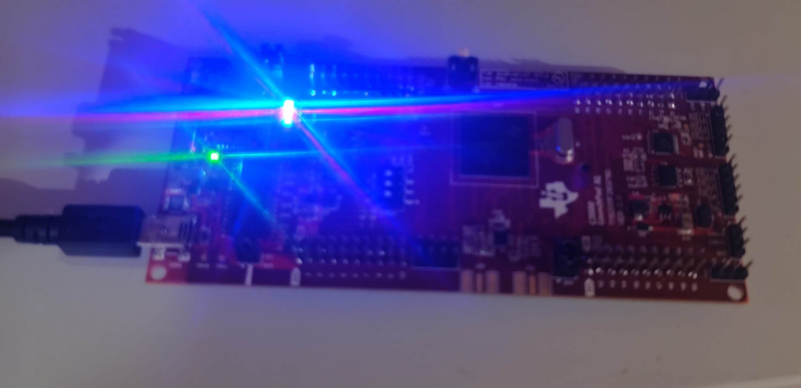
C2000™LAUNCHXL-F28379DLaunchPad™是一款完整的低成本开发板,LAUNCHXL-F28379D包含开发基于 F2837xD 微控制器的应用程序所需的所有硬件和软件。
软件安装
TI Code Composer Studio (CCS):用于为 C2000 系列设备开发代码的集成开发环境 (IDE)。
**C2000Ware 软件开发包 (SDK):**包括低级驱动程序、高度优化的库和软件示例,可用于开始使用 C2000 系列器件。
启动 CCS 环境
创建工作区后,导入空项目。
从 C2000Ware DriverLib 示例中导入一个空项目。转到 CCS 并找到到File→ Import…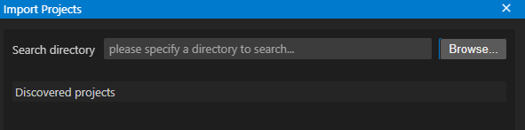
点击Browse,找到C2000ware的安装路径,导入对应开发板比如LAUNCHXL-F28379D的一个空白的项目 [C2000ware Install_dir]/driverlib/[device]/examples/empty_projects.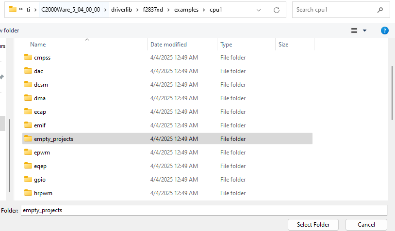
选择完后会看到空项目里有两个项目,选择上面的是C语言,下面的cpp是C++;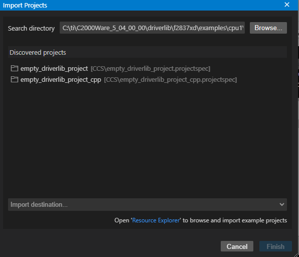
现在可以在工作区间看到导入的空项目,点击main函数,就可以添加自定义代码。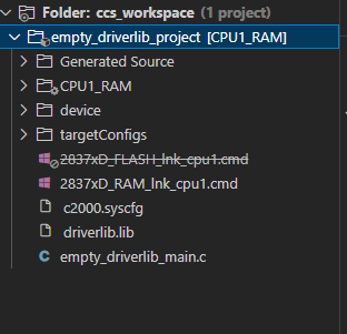
Debug调试时,确保正确的目标配置文件(“.ccxml ”文件)处于 “Active ”状态。右键单击项目并选择 “Rebuild”。在 “Console Output ”窗口中,项目应为零错误。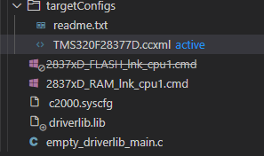
闪烁 LED 的编程
在本次实验中,将使用 C2000Ware DriverLib 应用程序编程接口(API)。双击 “main.c ”文件。
- 在 main() 函数中复制以下代码,初始化设备时钟和设备外设。
// Device Initialization
Device_init();
- 复制以下代码初始化 LED GPIO 引脚,并将 GPIO 引脚配置为推挽输出(push-pull output)。
// Initialize GPIO and configure the GPIO pin as a push-pull output
Device_initGPIO();
GPIO_setPadConfig(DEVICE_GPIO_PIN_LED1, GPIO_PIN_TYPE_STD);
GPIO_setDirectionMode(DEVICE_GPIO_PIN_LED1, GPIO_DIR_MODE_OUT);
- 现在复制以下代码,配置中断控制器和中断服务例程。
// Initialize PIE and clear PIE registers. Disables CPU interrupts.
Interrupt_initModule();
// Initialize the PIE vector table
Interrupt_initVectorTable();
// Enable Global Interrupt (INTM) and realtime interrupt (DBGM)
EINT;
ERTM;
- 复制下面的代码,创建一个无限循环,以一定的延迟切换 LED 对应的GPIO。切换频率可以通过延迟参数来控制。
// Loop Forever
for(;;)
{
    // Turn on LED
    GPIO_writePin(DEVICE_GPIO_PIN_LED1, 0);
    // Delay for a bit.
    DEVICE_DELAY_US(500000);
    // Turn off LED
    GPIO_writePin(DEVICE_GPIO_PIN_LED1, 1);
    // Delay for a bit.
    DEVICE_DELAY_US(500000);
}
右键单击项目并重建项目。然后 Run → Debug,加载并运行目标代码。使用红色方形停止按钮终止调试会话,然后关闭项目。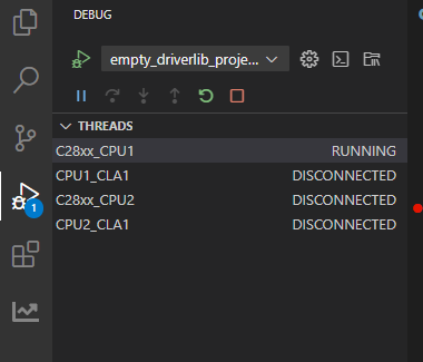
整个代码如下:
//
// Included Files
//
#include "driverlib.h"
#include "device.h"
#include "board.h"
#include "c2000ware_libraries.h"

//
// Main
//
void main(void)
{

    //
    // Initialize device clock and peripherals
    //
    Device_init();

    //
    // Disable pin locks and enable internal pull-ups.
    //
    Device_initGPIO();
    GPIO_setPadConfig(DEVICE_GPIO_PIN_LED1, GPIO_PIN_TYPE_STD);
    GPIO_setDirectionMode(DEVICE_GPIO_PIN_LED1, GPIO_DIR_MODE_OUT);
    //
    // Initialize PIE and clear PIE registers. Disables CPU interrupts.
    //
    Interrupt_initModule();

    //
    // Initialize the PIE vector table with pointers to the shell Interrupt
    // Service Routines (ISR).
    //
    Interrupt_initVectorTable();

    //
    // PinMux and Peripheral Initialization
    //
    Board_init();

    //
    // C2000Ware Library initialization
    //
    C2000Ware_libraries_init();

    //
    // Enable Global Interrupt (INTM) and real time interrupt (DBGM)
    //
    EINT;
    ERTM;

    while(1)
    {
    // Turn on LED
    GPIO_writePin(DEVICE_GPIO_PIN_LED1, 0);
    // Delay for a bit.
    DEVICE_DELAY_US(500000);
    // Turn off LED
    GPIO_writePin(DEVICE_GPIO_PIN_LED1, 1);
    // Delay for a bit.
    DEVICE_DELAY_US(500000);
    }
}

//
// End of File
//

智能硬件社区聚焦AI智能硬件技术生态,汇聚嵌入式AI、物联网硬件开发者,打造交流分享平台,同步全国赛事资讯、开展 OPC 核心人才招募,助力技术落地与开发者成长。
更多推荐


 9
9 0
0- 0


 已为社区贡献6条内容

所有评论(0)