[Example][TC397以太网例程详解] - 11.RTL8211F 复位
Aurix TriCore TC397 以太网官方例程
关键词
TC397 官方例程;TC397 以太网例程;TC397 GETH;
简介
本篇为 Aurix TriCore TC397 以太网官方例程分析,重点关注其硬件行为
调试所用的开发板型号:KIT-A2G-TC397-5V-TFT
所使用的例程:Ethernet_1_KIT_TC397_TFT
英飞凌 TriCore 官方例程下载地址:
https://github.com/Infineon/AURIX_code_examples
系列文章链接
TC397以太网例程 - 17.ECHO 应用 - 轮询定时器
TC397以太网例程 - 18.ECHO 应用 - 接收报文
目录
// 函数调用栈
core0_main()
    |--> Ifx_Lwip_init()
        |--> netif_add()
            |--> ifx_netif_init()
                |--> low_level_init() // 硬件初始化
初始化 GETH 模块和 RTL8211F 前需要重启 RTL8211F,确保初始化前 PHY 已就绪:
// Libraries/Ethernet/lwip/port/src/netif.c
static void low_level_init(netif_t *netif)
{
    ...
        /* first we reset our phy manually,
         * to make sure that the phy is ready when we init our module */
        {
// ------------------------------------------------------
            // 使能 GETH 模块
            IfxGeth_enableModule(&MODULE_GETH);
// ------------------------------------------------------

// ------------------------------------------------------
            // MDC 管理数据时钟引脚设置
            IfxPort_setPinModeOutput(ETH_MDC_PIN.pin.port,
                                    ETH_MDC_PIN.pin.pinIndex,
                                    IfxPort_OutputMode_pushPull,
                                    ETH_MDC_PIN.select);
// ------------------------------------------------------

// ------------------------------------------------------
            // 设置 MDIO 引脚
            GETH_GPCTL.B.ALTI0  = ETH_MDIO_PIN.inSelect;
// ------------------------------------------------------

// ------------------------------------------------------
            // 重启 RTL8211F
            while (GETH_MAC_MDIO_ADDRESS.B.GB) {};
            // first we wait that we are able to communicate with the Phy
            do
            {
                GETH_MAC_MDIO_ADDRESS.U = (0 << 21) | (0 << 16) | (0 << 8) | (3 << 2) | (1 << 0);
                while (GETH_MAC_MDIO_ADDRESS.B.GB) {};
            } while (GETH_MAC_MDIO_DATA.U & 0x8000); // wait for reset to finish
            // reset PHY
            // put data
            GETH_MAC_MDIO_DATA.U = 0x8000; // 发送复位请求
            GETH_MAC_MDIO_ADDRESS.U = (0 << 21) | (0 << 16) | (0 << 8) |  (1 << 2) | (1 << 0);
            while (GETH_MAC_MDIO_ADDRESS.B.GB) {};

            do
            {
                GETH_MAC_MDIO_ADDRESS.U = (0 << 21) | (0 << 16) | (0 << 8) | (3 << 2) | (1 << 0);
                while (GETH_MAC_MDIO_ADDRESS.B.GB) {};
            } while (GETH_MAC_MDIO_DATA.U & 0x8000);  // wait for reset to finish
// ------------------------------------------------------
        }
1.使能 GETH 模块
重启 RTL8211F 前,先确保 GETH 模块已使能,IfxGeth_enableModule() 检查 GETH 模块是否已使能,若未使能则会发送使能请求:
// Libraries/Ethernet/lwip/port/src/netif.c
static void low_level_init(netif_t *netif)
{
    ...
        /* first we reset our phy manually,
         * to make sure that the phy is ready when we init our module */
        {
            // 使能 GETH 模块
            IfxGeth_enableModule(&MODULE_GETH);
----------------------------------------------------------------------------------

// Libraries/iLLD/TC39B/Tricore/Geth/Std/IfxGeth.c
void IfxGeth_enableModule(Ifx_GETH *gethSFR)
{
    uint16 psw = IfxScuWdt_getCpuWatchdogPassword();

    // GETH 模块是否已使能
    if (IfxGeth_isModuleEnabled(gethSFR) != 1) /* if module is not enabled already */
    {    // 若模块未使能则发送使能请求
        IfxScuWdt_clearCpuEndinit(psw);        /* clears the endinit protection*/
        gethSFR->CLC.B.DISR = 0;               /* set the enable request */
        IfxScuWdt_setCpuEndinit(psw);          /* sets the endinit protection back on*/
    }
    // 再次检查模块是否使能
    IfxGeth_isModuleEnabled(gethSFR);          /* read back to ensure proper enabling */
        |--> return (gethSFR->CLC.B.DISS == 0) ? 1 : 0;
}
时钟控制寄存器 CLC( Clock Control Register)的初始值为 0x00000003:
-
CLC.DISR = 1:为 1 表示发送模块禁用请求;
-
CLC.DISS = 1:为 1 表示当前模块为禁用状态;
模块初始状态为禁用(CLC.DISS = 1),需要向 CLC.DISR 写 0 启用模块,模块启用后,会设置 CLC.DISS == 0
IfxGeth_isModuleEnabled() 读取 GETH 模块的 CLC.DISS 寄存器位,检查模块状态(是否已使能,使能为 "0")
若模块未使能则设置 CLC.DISR = 0 发送使能请求,需要注意的是,模块使能请求是写 "0",而不是写 "1",同样的,模块状态也是使能为 "0",未使能为 "1"
2.MDC 引脚设置
RGMII 接口的 MDC 引脚(Management Data Clock)用于接收 MDIO 数据管理引脚所需的时钟信号
IfxPort_setPinModeOutput() 将该引脚设置为 Push-pull 模式(推挽模式,可以输出高电平或低电平):
// Libraries/iLLD/TC39B/Tricore/Port/Std/IfxPort.h
/* Defines a pin */
typedef struct
{
    Ifx_P *port;
    uint8  pinIndex;
} IfxPort_Pin;
---------------------------------------------------------------------

// Libraries/iLLD/TC39B/Tricore/_PinMap/IfxGeth_PinMap.h
/* MDC pin mapping structure */
typedef const struct
{
    Ifx_GETH*         module;   /* Base address */
    IfxPort_Pin       pin;      /* Port pin */
    IfxPort_OutputIdx select;   /* Port control code */
} IfxGeth_Mdc_Out;
---------------------------------------------------------------------

// Libraries/iLLD/TC39B/Tricore/_PinMap/IfxGeth_PinMap.c
IfxGeth_Mdc_Out IfxGeth_MDC_P12_0_OUT = {&MODULE_GETH,
                                        {&MODULE_P12, 0},
                                        IfxPort_OutputIdx_alt6};
---------------------------------------------------------------------

// Configurations/Configuration.h
#define ETH_MDC_PIN  IfxGeth_MDC_P12_0_OUT
---------------------------------------------------------------------

// Libraries/Ethernet/lwip/port/src/netif.c
static void low_level_init(netif_t *netif)
{
    ...
        /* first we reset our phy manually,
         * to make sure that the phy is ready when we init our module */
        {
            ...
            // 设置 MDC 引脚的信号模式:推挽模式(高/低电平)
            IfxPort_setPinModeOutput(ETH_MDC_PIN.pin.port,
                                     ETH_MDC_PIN.pin.pinIndex,
                                     IfxPort_OutputMode_pushPull,
                                     ETH_MDC_PIN.select);
其中,MDC 引脚的输出模式,设置为 IfxPort_OutputMode_pushPull 推挽模式,该模式的引脚既可以输出高电平,也可以输出低电平
此外,TC397 的一些引脚还支持 IfxPort_OutputMode_openDrain 开漏输出模式,即引脚有信号时输出低电平,无信号时为高阻态(相当于断路)
3.MDIO 引脚设置
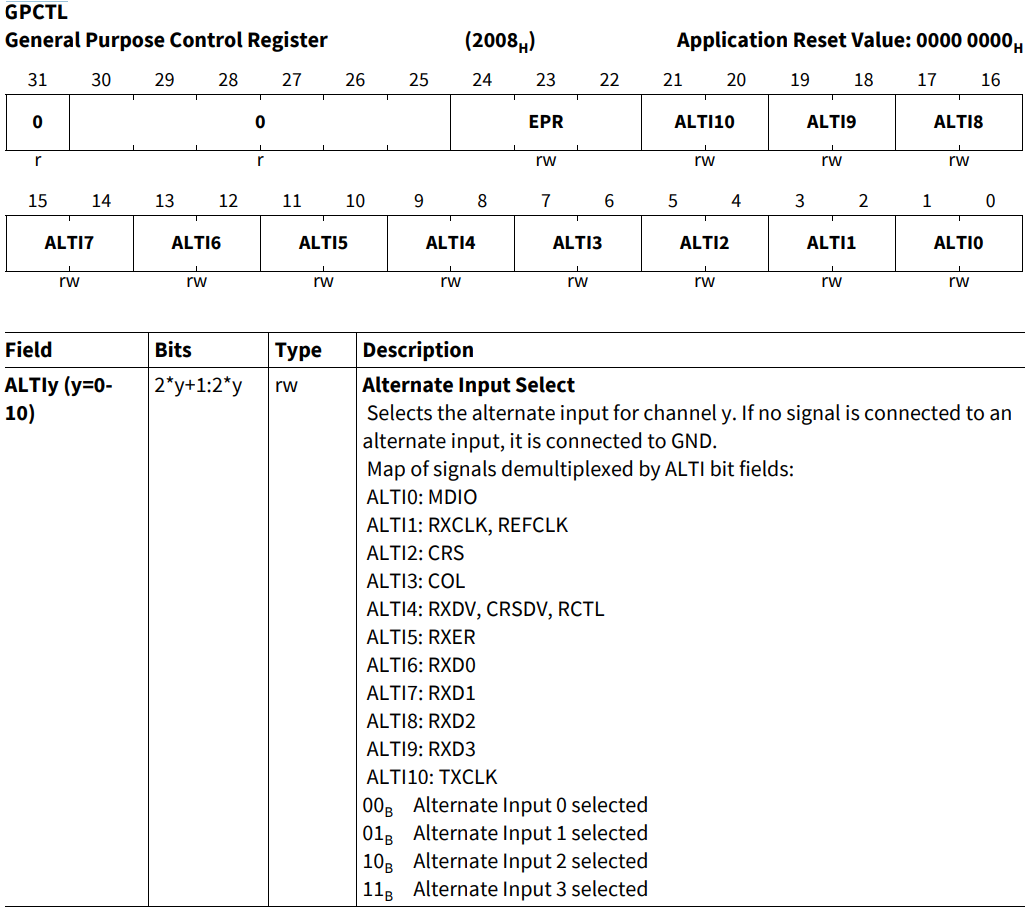
MDIO 引脚用于传输控制和状态信息,将 RTL8211F 的 MDIO 引脚与 GETH 模块的 GPCTL.ALTI0 相连:
// Configurations/Configuration.h
#define ETH_MDIO_PIN                IfxGeth_MDIO_P12_1_INOUT
--------------------------------------------------------------------------

// Libraries/iLLD/TC39B/Tricore/_PinMap/IfxGeth_PinMap.c
IfxGeth_Mdio_InOut IfxGeth_MDIO_P12_1_INOUT = {&MODULE_GETH,
                                              {&MODULE_P12, 1},
                                              Ifx_RxSel_c,
                                              IfxPort_OutputIdx_general};
--------------------------------------------------------------------------

// Libraries/Ethernet/lwip/port/src/netif.c
static void low_level_init(netif_t *netif)
{
    ...
        /* first we reset our phy manually,
         * to make sure that the phy is ready when we init our module */
        {
            ...
            // 设置 MDIO 引脚
            GETH_GPCTL.B.ALTI0  = ETH_MDIO_PIN.inSelect;
GPCTL 为 GETH 模块的通用控制寄存器,其相关位与 RTL8211F 的引脚关联,即通过向这些位写值,会将数据通过引脚发送至 RTL8211F,相关控制位的描述如下所示:
4.RTL8211F 复位
MAC_MDIO_ADDRESS.GB 用于通知 RTL8211F 准备写入/读取 MDIO 寄存器,仅当 GB == 0 时才允许操作 MAC_MDIO_Address 和 MAC_MDIO_Data 寄存器,当前数据帧发送/接收完成后,MAC 会将其重置为 "0"
向 GETH_MAC_MDIO_DATA 寄存器写入 0x8000 重启 RTL8211F:
// Libraries/Ethernet/lwip/port/src/netif.c
static void low_level_init(netif_t *netif)
{
    ...
        /* first we reset our phy manually,
         * to make sure that the phy is ready when we init our module */
        {
            ...
            // MDIO Tx/Rx 是否已完成 GB == 0
            while (GETH_MAC_MDIO_ADDRESS.B.GB) {};

// --------------------------------------------------------------------
            // first we wait that we are able to communicate with the Phy
            do
            {
                GETH_MAC_MDIO_ADDRESS.U = (0 << 21) | (0 << 16) | (0 << 8) | (3 << 2) | (1 << 0);
                // MDIO Tx/Rx 是否已完成 GB == 0
                while (GETH_MAC_MDIO_ADDRESS.B.GB) {};
            } while (GETH_MAC_MDIO_DATA.U & 0x8000); // wait for reset to finish
// --------------------------------------------------------------------

// --------------------------------------------------------------------
            // reset PHY
            // put data
            GETH_MAC_MDIO_DATA.U = 0x8000; // 发送复位请求
            GETH_MAC_MDIO_ADDRESS.U = (0 << 21) | (0 << 16) | (0 << 8) | (1 << 2) | (1 << 0);
// --------------------------------------------------------------------

            // MDIO Tx/Rx 是否已完成 GB == 0
            while (GETH_MAC_MDIO_ADDRESS.B.GB) {};

// --------------------------------------------------------------------
            do
            {
                GETH_MAC_MDIO_ADDRESS.U = (0 << 21) | (0 << 16) | (0 << 8) | (3 << 2) | (1 << 0);
                // MDIO Tx/Rx 是否已完成 GB == 0
                while (GETH_MAC_MDIO_ADDRESS.B.GB) {};
            } while (GETH_MAC_MDIO_DATA.U & 0x8000); // wait for reset to finish
// --------------------------------------------------------------------
        }
其中,MAC_MDIO_ADDRESS 寄存器位的操作如下:
-
(0 << 21):PA (Physical Layer Address),物理地址;
-
(0 << 16):RDA(Register/Device Address),寄存器/设备地址;
-
(0 << 8):CR(CSR Clock Range),设置 MDC 时钟频率:
-
写入 "0" 表示 CSR Clock = 60 - 100 MHz,MDC Clock = CSR Clock / 42;
-
-
(1 << 2):GOC_0(GMII Operation Command 0),操作指令的低位,和 GOC_1 共同确定 PHY 的行为;
-
(1 << 2):GOC_1(GMII Operation Command 1),操作指令的高位,和 GOC_0 共同确定 PHY 的行为;
-
GOC_0 & GOC_1:值 0 1 为写入,值 1 1 为读取;
-
-
(1 << 0):GB(GMII Busy),MDIO 当前是否正在发送/读取数据,为 "1" 表示被占用;
MAC_MDIO_ADDRESS.RDA 写入值为 0x0,目标寄存器为 RTL8211F 的 BMCR 寄存器;
MAC_MDIO_DATA 寄存器的高 16 位为 PHY 的目标寄存器地址(仅 C45 使用,C22无效),低 16 位为需要写入寄存器的数据
这里写入的值为 0x8000,使用的模式为 C22,结合 MAC_MDIO_ADDRESS 寄存器,表示将 BMCR 寄存器的第 15 位置 1,即 PHY 复位:
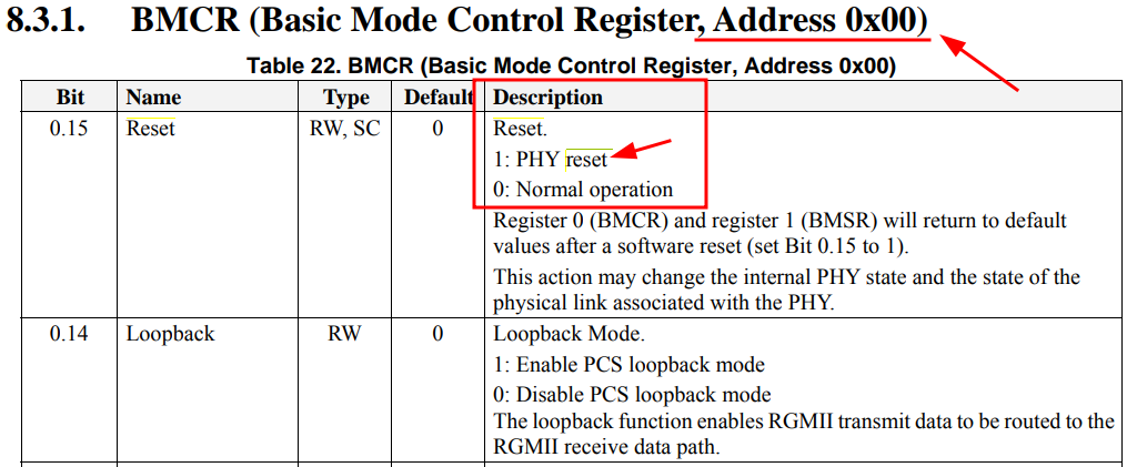
RTL8211F 复位完成后,会自动将 BMCR 的第 15 位恢复为 0

智能硬件社区聚焦AI智能硬件技术生态,汇聚嵌入式AI、物联网硬件开发者,打造交流分享平台,同步全国赛事资讯、开展 OPC 核心人才招募,助力技术落地与开发者成长。
更多推荐


 19
19 0
0- 0


 已为社区贡献21条内容

所有评论(0)