CubeMX配置入门串口实验1
本文介绍了基于STM32 CubeMX的串口通信实验配置过程。首先展示了串口和GPIO引脚在CubeMX中的配置步骤,包括USART1的启用和LED0输出模式的设置。然后详细讲解了HAL库中串口发送(HAL_UART_Transmit)和接收(HAL_UART_Receive)两个关键函数的参数说明与返回值定义。最后提供了自动生成的main.c文件框架,包含系统时钟配置和外设初始化代码,为后续编写
·
串口入门实验1
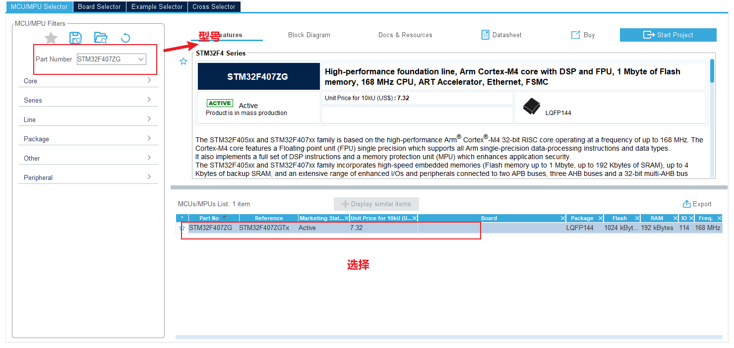
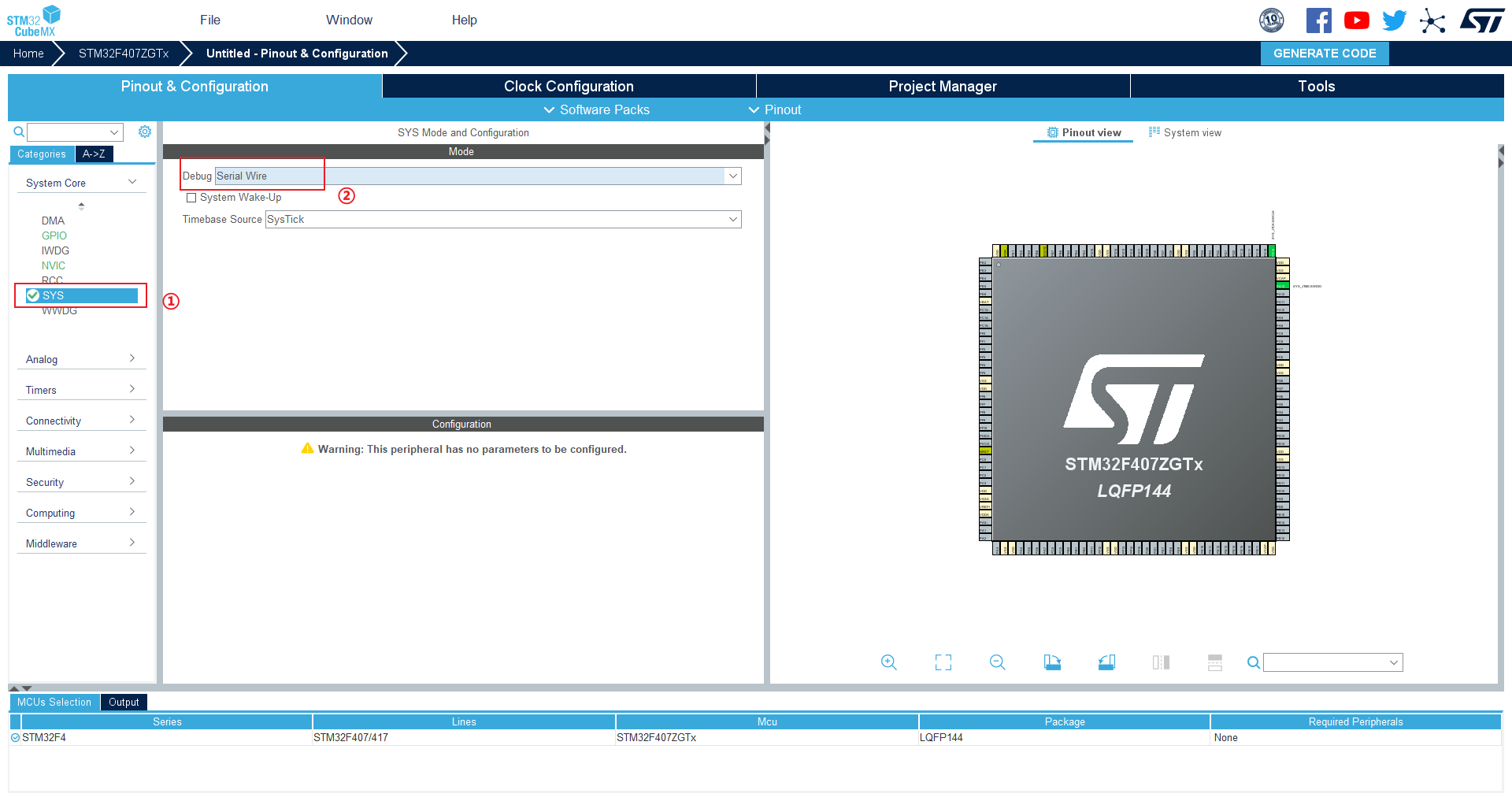
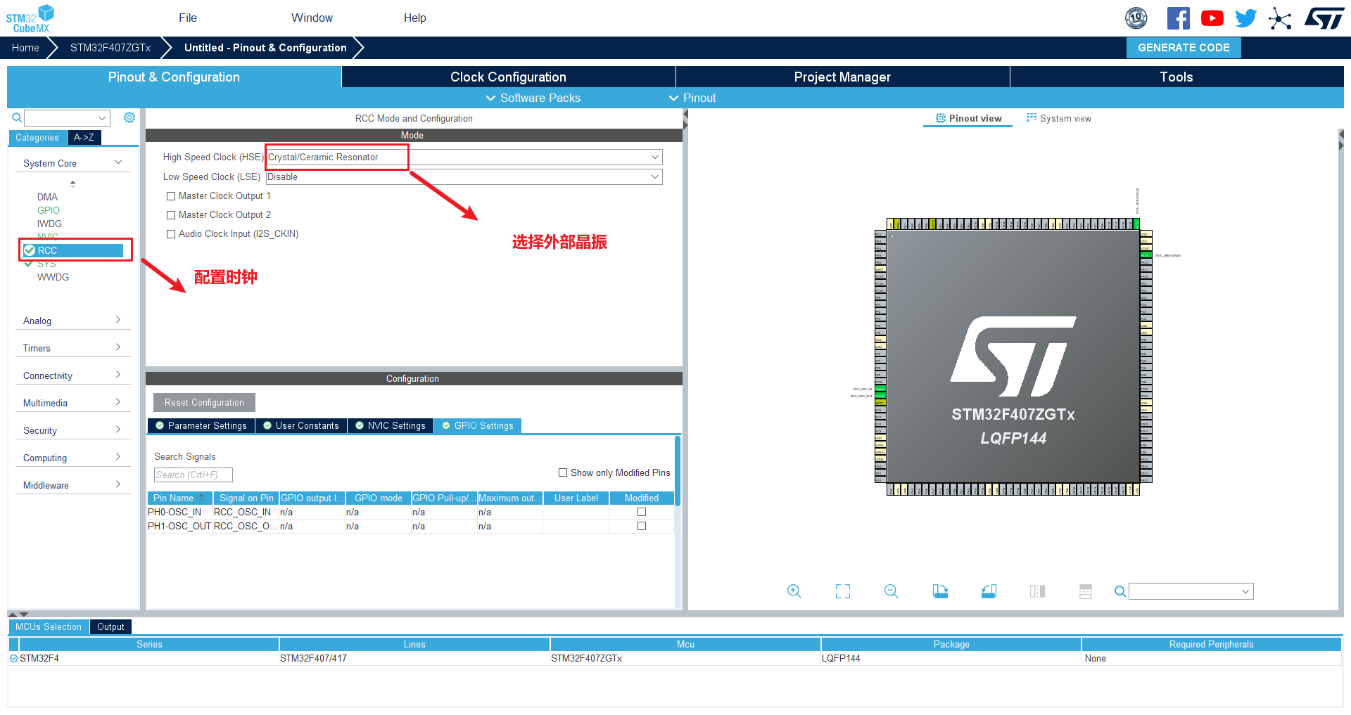
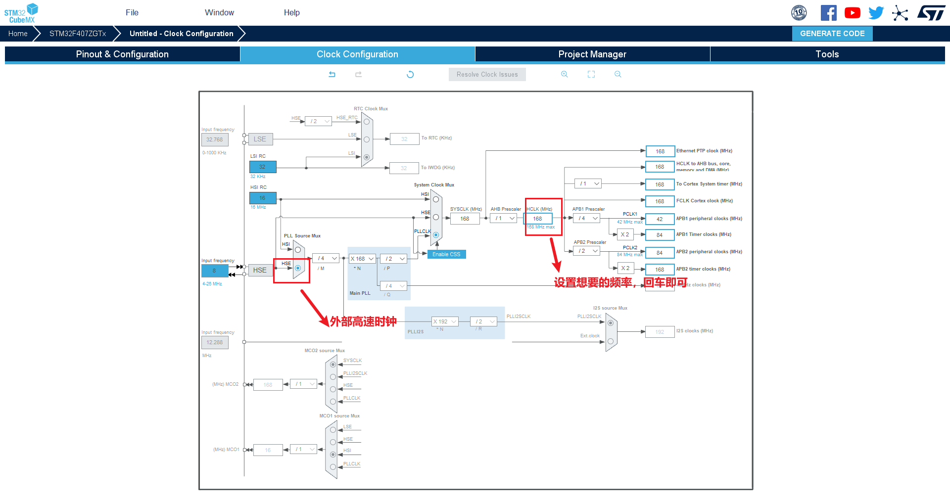
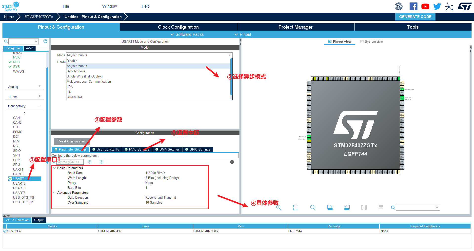
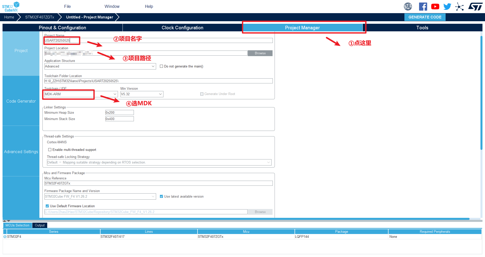
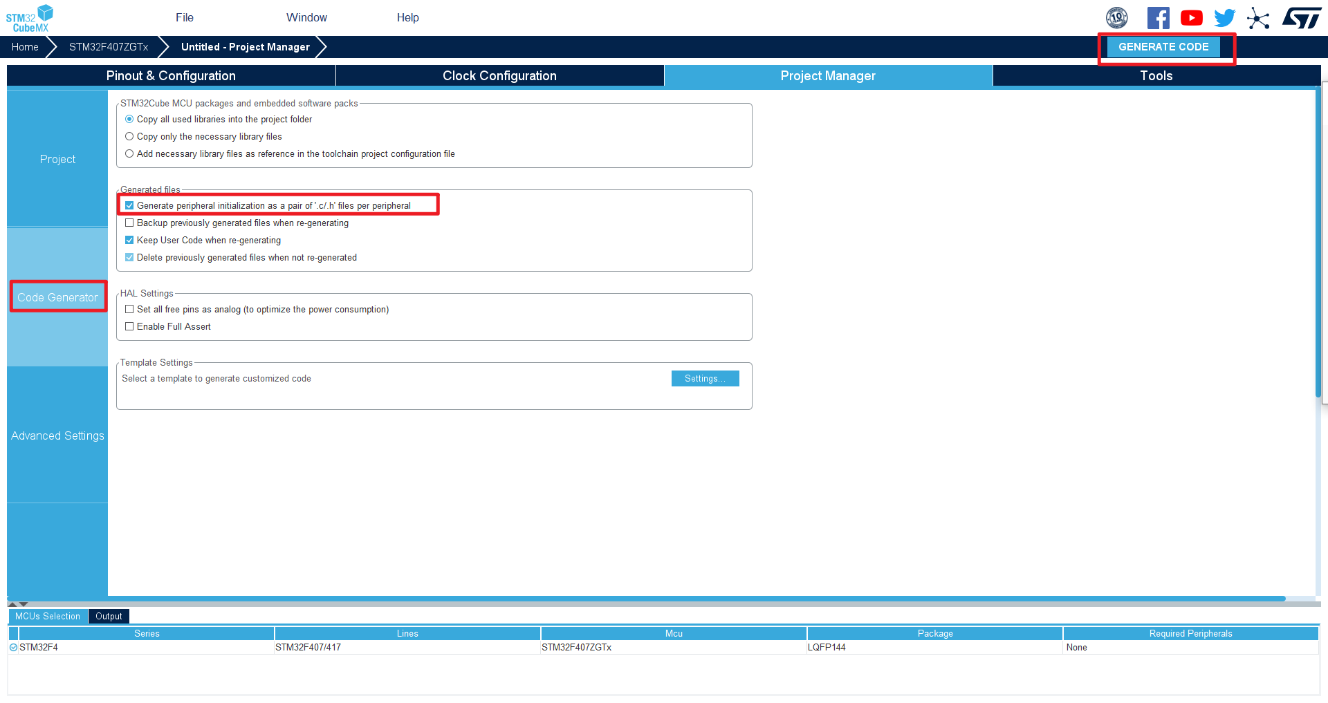
1、CubeMX配置
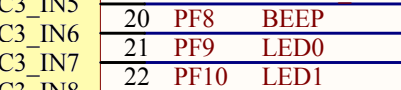
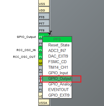
选LED0,设置为输出模式
2、串口发送接收函数
HAL_StatusTypeDef HAL_UART_Receive(UART_HandleTypeDef *huart, uint8_t *pData, uint16_t Size, uint32_t Timeout)

    /*
    1、参数huart:串口句柄的指针
    2、参数pData:指向接收缓冲区的指针
    3、参数Size:要接收数据的数量,以字节为单位
    4、参数Timeout:超时时间,以ms为单位
    5、返回值:返回数据传输的结果(成功还是失败)
            typedef enum
            {
              HAL_OK       = 0x00U,  	//成功
              HAL_ERROR    = 0x01U,		//接收出错
              HAL_BUSY     = 0x02U,		//串口忙
              HAL_TIMEOUT  = 0x03U		//接收超时
            } HAL_StatusTypeDef;

    */
HAL_StatusTypeDef HAL_UART_Transmit(UART_HandleTypeDef *huart, uint8_t *pData, uint16_t Size, uint32_t Timeout)

	/*
    1、参数huart:串口句柄的指针
    2、参数pData:指向发送数据的指针
    3、参数Size:要发送数据的数量,以字节为单位
    4、参数Timeout:超时时间,以ms为单位
    5、返回值:返回数据传输的结果(成功还是失败)
            typedef enum
            {
              HAL_OK       = 0x00U,  	//成功
              HAL_ERROR    = 0x01U,		//接收出错
              HAL_BUSY     = 0x02U,		//串口忙
              HAL_TIMEOUT  = 0x03U		//接收超时
            } HAL_StatusTypeDef;

    */
3、简单发送,接收数据
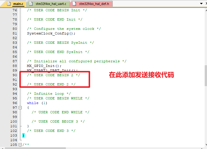
编写cubemx生成的代码:
自动生成的main函数:
/* USER CODE BEGIN Header */
/**
******************************************************************************
* @file : main.c
* @brief : Main program body
******************************************************************************
* @attention
*
* <h2><center>© Copyright (c) 2025 STMicroelectronics.
* All rights reserved.</center></h2>
*
* This software component is licensed by ST under BSD 3-Clause license,
* the "License"; You may not use this file except in compliance with the
* License. You may obtain a copy of the License at:
* opensource.org/licenses/BSD-3-Clause
*
******************************************************************************
*/
/* USER CODE END Header */
/* Includes ------------------------------------------------------------------*/
#include "main.h"
#include "usart.h"
#include "gpio.h"
/* Private includes ----------------------------------------------------------*/
/* USER CODE BEGIN Includes */
/* USER CODE END Includes */
/* Private typedef -----------------------------------------------------------*/
/* USER CODE BEGIN PTD */
/* USER CODE END PTD */
/* Private define ------------------------------------------------------------*/
/* USER CODE BEGIN PD */
/* USER CODE END PD */
/* Private macro -------------------------------------------------------------*/
/* USER CODE BEGIN PM */
/* USER CODE END PM */
/* Private variables ---------------------------------------------------------*/
/* USER CODE BEGIN PV */
/* USER CODE END PV */
/* Private function prototypes -----------------------------------------------*/
void SystemClock_Config(void);
/* USER CODE BEGIN PFP */
/* USER CODE END PFP */
/* Private user code ---------------------------------------------------------*/
/* USER CODE BEGIN 0 */
/* USER CODE END 0 */
/**
* @brief The application entry point.
* @retval int
*/
int main(void)
{
/* USER CODE BEGIN 1 */
/* USER CODE END 1 */
/* MCU Configuration--------------------------------------------------------*/
/* Reset of all peripherals, Initializes the Flash interface and the Systick. */
HAL_Init();
/* USER CODE BEGIN Init */
/* USER CODE END Init */
/* Configure the system clock */
SystemClock_Config();
/* USER CODE BEGIN SysInit */
/* USER CODE END SysInit */
/* Initialize all configured peripherals */
MX_GPIO_Init();
MX_USART1_UART_Init();
/* USER CODE BEGIN 2 */
/* USER CODE END 2 */
/* Infinite loop */
/* USER CODE BEGIN WHILE */
while (1)
{
/* USER CODE END WHILE */
/* USER CODE BEGIN 3 */
}
/* USER CODE END 3 */
}
/**
* @brief System Clock Configuration
* @retval None
*/
void SystemClock_Config(void)
{
RCC_OscInitTypeDef RCC_OscInitStruct = {0};
RCC_ClkInitTypeDef RCC_ClkInitStruct = {0};
/** Configure the main internal regulator output voltage
*/
__HAL_RCC_PWR_CLK_ENABLE();
__HAL_PWR_VOLTAGESCALING_CONFIG(PWR_REGULATOR_VOLTAGE_SCALE1);
/** Initializes the RCC Oscillators according to the specified parameters
* in the RCC_OscInitTypeDef structure.
*/
RCC_OscInitStruct.OscillatorType = RCC_OSCILLATORTYPE_HSE;
RCC_OscInitStruct.HSEState = RCC_HSE_ON;
RCC_OscInitStruct.PLL.PLLState = RCC_PLL_ON;
RCC_OscInitStruct.PLL.PLLSource = RCC_PLLSOURCE_HSE;
RCC_OscInitStruct.PLL.PLLM = 4;
RCC_OscInitStruct.PLL.PLLN = 168;
RCC_OscInitStruct.PLL.PLLP = RCC_PLLP_DIV2;
RCC_OscInitStruct.PLL.PLLQ = 4;
if (HAL_RCC_OscConfig(&RCC_OscInitStruct) != HAL_OK)
{
Error_Handler();
}
/** Initializes the CPU, AHB and APB buses clocks
*/
RCC_ClkInitStruct.ClockType = RCC_CLOCKTYPE_HCLK|RCC_CLOCKTYPE_SYSCLK
|RCC_CLOCKTYPE_PCLK1|RCC_CLOCKTYPE_PCLK2;
RCC_ClkInitStruct.SYSCLKSource = RCC_SYSCLKSOURCE_PLLCLK;
RCC_ClkInitStruct.AHBCLKDivider = RCC_SYSCLK_DIV1;
RCC_ClkInitStruct.APB1CLKDivider = RCC_HCLK_DIV4;
RCC_ClkInitStruct.APB2CLKDivider = RCC_HCLK_DIV2;
if (HAL_RCC_ClockConfig(&RCC_ClkInitStruct, FLASH_LATENCY_5) != HAL_OK)
{
Error_Handler();
}
}
/* USER CODE BEGIN 4 */
/* USER CODE END 4 */
/**
* @brief This function is executed in case of error occurrence.
* @retval None
*/
void Error_Handler(void)
{
/* USER CODE BEGIN Error_Handler_Debug */
/* User can add his own implementation to report the HAL error return state */
__disable_irq();
while (1)
{
}
/* USER CODE END Error_Handler_Debug */
}
#ifdef USE_FULL_ASSERT
/**
* @brief Reports the name of the source file and the source line number
* where the assert_param error has occurred.
* @param file: pointer to the source file name
* @param line: assert_param error line source number
* @retval None
*/
void assert_failed(uint8_t *file, uint32_t line)
{
/* USER CODE BEGIN 6 */
/* User can add his own implementation to report the file name and line number,
ex: printf("Wrong parameters value: file %s on line %d\r\n", file, line) */
/* USER CODE END 6 */
}
#endif /* USE_FULL_ASSERT */
/************************ (C) COPYRIGHT STMicroelectronics *****END OF FILE****/
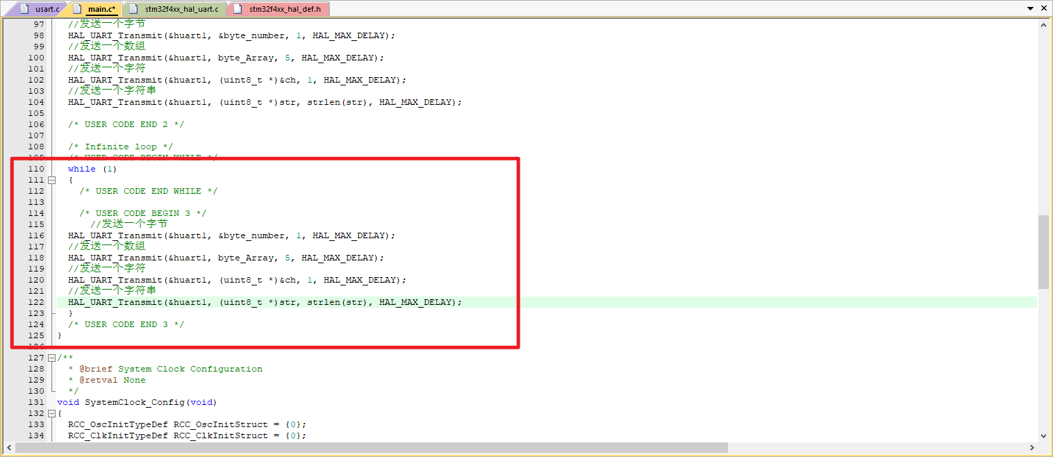
简单发送
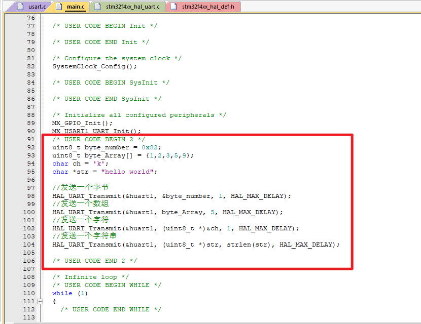
	uint8_t byte_number = 0x82;
	uint8_t byte_Array[] = {1,2,3,5,9};
	char ch = 'k';
	char *str = "hello world";

	//·¢ËÍÒ»¸ö×Ö½Ú
	HAL_UART_Transmit(&huart1, &byte_number, 1, HAL_MAX_DELAY);
	//·¢ËÍÒ»¸öÊý×é
	HAL_UART_Transmit(&huart1, byte_Array, 5, HAL_MAX_DELAY);
	//·¢ËÍÒ»¸ö×Ö·û
	HAL_UART_Transmit(&huart1, (uint8_t *)&ch, 1, HAL_MAX_DELAY);
	//·¢ËÍÒ»¸ö×Ö·û´®
	HAL_UART_Transmit(&huart1, (uint8_t *)str, strlen(str), HAL_MAX_DELAY);
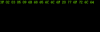
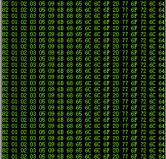
串口16进制接收
将发送放到while循环里,将一直向串口助手发数:
简单接收
接收到1,灯LED0亮
接收到0,灯LED0灭
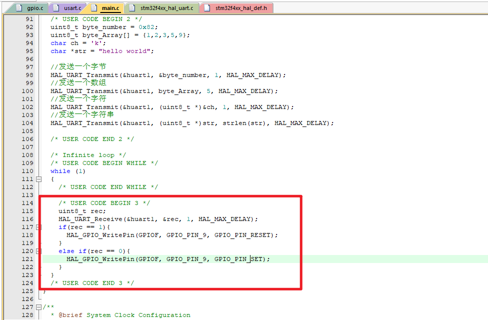
		uint8_t rec;
		HAL_UART_Receive(&huart1, &rec, 1, HAL_MAX_DELAY);
		if(rec == 1){
			HAL_GPIO_WritePin(GPIOF, GPIO_PIN_9, GPIO_PIN_RESET);
		}
		else if(rec == 0){
			HAL_GPIO_WritePin(GPIOF, GPIO_PIN_9, GPIO_PIN_SET);
		}
更多串口详细内容,请见:【STM32学习笔记】串口总结:轮询模式、中断模式、DMA模式以及串口接收不定长数据

智能硬件社区聚焦AI智能硬件技术生态,汇聚嵌入式AI、物联网硬件开发者,打造交流分享平台,同步全国赛事资讯、开展 OPC 核心人才招募,助力技术落地与开发者成长。
更多推荐


 10
10 0
0- 0


 已为社区贡献8条内容

所有评论(0)