MaixCAM教程5:MSPM0G3507与MaixCAM的串口通信
该代码只负责展示相关逻辑(检测person来控制g3507上面的pwm灯)
·
MSPM0G3507天猛星、MaixCAM有屏幕版
该代码只负责展示相关逻辑(检测person来控制g3507上面的pwm灯)
接线如下
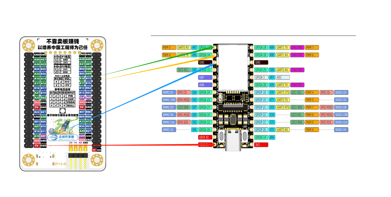
MaixCAM代码:
from maix import camera, display, image, nn, app, uart, pinmap
import time

# 设置 UART1 的引脚映射
pinmap.set_pin_function("A17", "UART0_RX")
pinmap.set_pin_function("A16", "UART0_TX")

# 初始化串口 - 使用 /dev/ttyS1
serial1 = uart.UART("/dev/ttyS0", 9600)

detector = nn.YOLOv5(model="/root/models/yolov5s.mud", dual_buff=True)
cam = camera.Camera(detector.input_width(), detector.input_height(), detector.input_format())
disp = display.Display()

# 获取 person 的类别 ID
person_id = 0
for i, label in enumerate(detector.labels):
    if "person" in label.lower():
        person_id = i
        print(f"Person class ID: {person_id}")
        break

# 用于跟踪上次发送状态
last_detected = False

while not app.need_exit():
    img = cam.read()
    objs = detector.detect(img, conf_th=0.5, iou_th=0.45)

    # 检测是否有符合条件的人
    current_detected = False

    for obj in objs:
        if obj.class_id == person_id and obj.score >= 0.7:
            current_detected = True
            img.draw_rect(obj.x, obj.y, obj.w, obj.h, color=image.COLOR_RED)
            msg = f'Person: {obj.score:.2f}'
            img.draw_string(obj.x, obj.y, msg, color=image.COLOR_RED)
        else:
            img.draw_rect(obj.x, obj.y, obj.w, obj.h, color=image.COLOR_BLUE)
            msg = f'{detector.labels[obj.class_id]}: {obj.score:.2f}'
            img.draw_string(obj.x, obj.y, msg, color=image.COLOR_BLUE)

    # 当检测状态变化时发送消息
    if current_detected and not last_detected:
        print("Detected person with confidence > 0.7")
        serial1.write_str("helloperson\n")
        print("UART sent: helloperson")

    # 更新状态
    last_detected = current_detected

    disp.show(img)
SYSCONFIG相关配置如下:
/**
 * These arguments were used when this file was generated. They will be automatically applied on subsequent loads
 * via the GUI or CLI. Run CLI with '--help' for additional information on how to override these arguments.
 * @cliArgs --device "MSPM0G350X" --part "Default" --package "LQFP-64(PM)" --product "mspm0_sdk@2.05.00.05"
 * @v2CliArgs --device "MSPM0G3507" --package "LQFP-64(PM)" --product "mspm0_sdk@2.05.00.05"
 * @versions {"tool":"1.24.0+4150"}
 */

/**
 * Import the modules used in this configuration.
 */
const Board         = scripting.addModule("/ti/driverlib/Board");
const GPIO          = scripting.addModule("/ti/driverlib/GPIO", {}, false);
const GPIO1         = GPIO.addInstance();
const PWM           = scripting.addModule("/ti/driverlib/PWM", {}, false);
const PWM1          = PWM.addInstance();
const SYSCTL        = scripting.addModule("/ti/driverlib/SYSCTL");
const UART          = scripting.addModule("/ti/driverlib/UART", {}, false);
const UART1         = UART.addInstance();
const ProjectConfig = scripting.addModule("/ti/project_config/ProjectConfig");

/**
 * Write custom configuration values to the imported modules.
 */
const divider6       = system.clockTree["PLL_CLK2X_DIV"];
divider6.divideValue = 4;

const gate7  = system.clockTree["MFCLKGATE"];
gate7.enable = true;


GPIO1.$name                         = "PORTA";
GPIO1.port                          = "PORTA";
GPIO1.associatedPins.create(2);
GPIO1.associatedPins[0].$name       = "SCL2";
GPIO1.associatedPins[0].pin.$assign = "PA8";
GPIO1.associatedPins[1].$name       = "SDA2";
GPIO1.associatedPins[1].pin.$assign = "PA26";

PWM1.$name                      = "PWM_0";
PWM1.clockDivider               = 8;
PWM1.timerStartTimer            = true;
PWM1.ccIndex                    = [1];
PWM1.peripheral.$assign         = "TIMG8";
PWM1.peripheral.ccp1Pin.$assign = "PB22";
PWM1.PWM_CHANNEL_1.$name        = "ti_driverlib_pwm_PWMTimerCC0";
PWM1.ccp1PinConfig.$name        = "ti_driverlib_gpio_GPIOPinGeneric0";

SYSCTL.clockTreeEn = true;

UART1.$name                    = "UART_0";
UART1.rxFifoThreshold          = "DL_UART_RX_FIFO_LEVEL_ONE_ENTRY";
UART1.txFifoThreshold          = "DL_UART_TX_FIFO_LEVEL_ONE_ENTRY";
UART1.enableDMATX              = false;
UART1.enabledInterrupts        = ["RX"];
UART1.peripheral.$assign       = "UART0";
UART1.peripheral.rxPin.$assign = "PA11";
UART1.peripheral.txPin.$assign = "PA10";
UART1.txPinConfig.$name        = "ti_driverlib_gpio_GPIOPinGeneric7";
UART1.rxPinConfig.$name        = "ti_driverlib_gpio_GPIOPinGeneric8";

ProjectConfig.genDisable = true;
scripting.suppress("Project Configuration File generation is disabled for this project\\. SysConfig Project Migration is not currently supported for this project\\.", ProjectConfig);

/**
 * Pinmux solution for unlocked pins/peripherals. This ensures that minor changes to the automatic solver in a future
 * version of the tool will not impact the pinmux you originally saw.  These lines can be completely deleted in order to
 * re-solve from scratch.
 */
Board.peripheral.$suggestSolution          = "DEBUGSS";
Board.peripheral.swclkPin.$suggestSolution = "PA20";
Board.peripheral.swdioPin.$suggestSolution = "PA19";
MSPM0G3507代码:
#include "ti_msp_dl_config.h"
#include <string.h>

// 串口接收相关变量
#define RX_BUFFER_SIZE 32
#define TARGET_STRING "helloperson"
volatile uint8_t rxBuffer[RX_BUFFER_SIZE];
volatile uint8_t rxIndex = 0;
volatile bool stringReceived = false;

// PWM呼吸灯相关变量
volatile bool breathingEnabled = false;
volatile uint16_t pwmDutyCycle = 0;
volatile int16_t pwmDirection = 1;  // 1为递增,-1为递减
volatile uint16_t breathingSpeed = 5;  // 呼吸灯变化速度

// 定时器计数器(用于控制呼吸灯速度)
volatile uint32_t timerCounter = 0;

int main(void)
{
    // 系统初始化
    SYSCFG_DL_init();

    // 使能全局中断
    NVIC_EnableIRQ(UART_0_INST_INT_IRQN);
    __enable_irq();

    // 初始化PWM占空比为0(关闭状态)
    DL_TimerG_setCaptureCompareValue(PWM_0_INST, 1000, DL_TIMER_CC_1_INDEX);

    while (1) {
        // 检查是否接收到目标字符串
        if (stringReceived) {
            stringReceived = false;

            // 切换呼吸灯状态
            breathingEnabled = !breathingEnabled;

            if (!breathingEnabled) {
                // 关闭呼吸灯,设置PWM占空比为0(灯完全不亮)
                pwmDutyCycle = 0;
                DL_TimerG_setCaptureCompareValue(PWM_0_INST, 1000, DL_TIMER_CC_1_INDEX);
            } else {
                // 开启呼吸灯,重置呼吸灯参数
                pwmDutyCycle = 0;
                pwmDirection = 1;
                timerCounter = 0;  // 重置计数器
            }
        }

        // 呼吸灯控制逻辑(仅在启用时运行)
        if (breathingEnabled) {
            timerCounter++;

            // 控制呼吸灯变化速度
            if (timerCounter >= 1000) {  // 可以调整这个值来改变呼吸频率
                timerCounter = 0;

                // 更新PWM占空比
                pwmDutyCycle += pwmDirection * breathingSpeed;

                // 检查边界并改变方向
                if (pwmDutyCycle >= 1000) {
                    pwmDutyCycle = 1000;
                    pwmDirection = -1;  // 开始递减
                } else if (pwmDutyCycle <= 0) {
                    pwmDutyCycle = 0;
                    pwmDirection = 1;   // 开始递增
                }

                // 设置新的PWM占空比(1000-pwmDutyCycle实现正常亮度控制)
                DL_TimerG_setCaptureCompareValue(PWM_0_INST, 1000 - pwmDutyCycle, DL_TIMER_CC_1_INDEX);
            }
        }

        // 延时,降低CPU占用率
        delay_cycles(1000);
    }
}

// UART中断服务函数
void UART_0_INST_IRQHandler(void)
{
    uint8_t receivedChar;  // 在函数开头声明变量

    switch (DL_UART_Main_getPendingInterrupt(UART_0_INST)) {
        case DL_UART_MAIN_IIDX_RX:
            // 接收到数据
            receivedChar = DL_UART_Main_receiveData(UART_0_INST);

            // 将接收到的字符存储到缓冲区
            if (rxIndex < RX_BUFFER_SIZE - 1) {
                rxBuffer[rxIndex] = receivedChar;
                rxIndex++;
                rxBuffer[rxIndex] = '\0';  // 添加字符串结束符
            }

            // 检查是否接收到完整的目标字符串
            if (rxIndex >= strlen(TARGET_STRING)) {
                // 检查缓冲区末尾是否匹配目标字符串
                if (strstr((char*)rxBuffer, TARGET_STRING) != NULL) {
                    stringReceived = true;
                    // 清空缓冲区
                    rxIndex = 0;
                    memset((void*)rxBuffer, 0, RX_BUFFER_SIZE);
                } else if (rxIndex >= RX_BUFFER_SIZE - 1) {
                    // 缓冲区满但没有匹配,清空缓冲区
                    rxIndex = 0;
                    memset((void*)rxBuffer, 0, RX_BUFFER_SIZE);
                }
            }
            break;

        default:
            break;
    }
}

// 可选:添加一个函数来设置呼吸灯的速度
void setBreathingSpeed(uint16_t speed) {
    if (speed > 0 && speed <= 50) {
        breathingSpeed = speed;
    }
}

// 可选:添加一个函数来获取当前呼吸灯状态
bool getBreathingState(void) {
    return breathingEnabled;
}
效果演示:
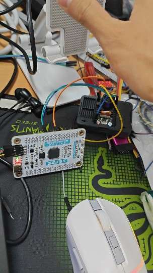
mspm0g3507和maixcom通信演示视频
注意:尽量UART0对UART0,否则传输不了数据!!!

智能硬件社区聚焦AI智能硬件技术生态,汇聚嵌入式AI、物联网硬件开发者,打造交流分享平台,同步全国赛事资讯、开展 OPC 核心人才招募,助力技术落地与开发者成长。
更多推荐


 17
17 0
0- 0


 已为社区贡献3条内容

所有评论(0)