【ESP32】ESP32-P4 通过 SDIO 连接 ESP32-C6
参考链接:
ESP32P4外接ESP32C6连接WIFI
ESP-Hosted on the ESP32-P4-Function-EV-Board DevKit
1. ESP32-C6 编译烧录固件
ESP32-P4-Function-EV-Board 板卡中的 ESP32-C6 默认烧录的是 ESP-Hosted-MCU 的 slave 固件(版本 0.0.6)。该固件使 ESP32-C6 作为通信协处理器,通过 SDIO 接口为板上的 ESP32-P4 主控提供 Wi-Fi 连接能力。官方文档明确说明出厂时 ESP32-C6 已预烧录此固件,用户如需更新可通过 OTA 或 ESP-Prog 重新烧录新版 ESP-Hosted slave 固件【如需升级或自定义,可参考官方 ESP-Hosted-MCU 项目文档】ESP-Hosted on the ESP32-P4-Function-EV-Board DevKit。
如需烧录其他固件(如 ESP-AT),则需手动操作,默认出厂固件为 ESP-Hosted-MCU slave 固件。
新买的ESP32-C6没有固件,需要通过ESP-Prog烧录 ESP-Hosted-MCU slave 固件。
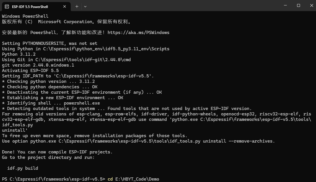
1.1. 打开 ESP-IDF 5.5 PowerShell

切换路径
cd E:\HBYT_Code\Demo
1.2. Check out the ESP-Hosted slave example project
idf.py create-project-from-example "espressif/esp_hosted:slave"

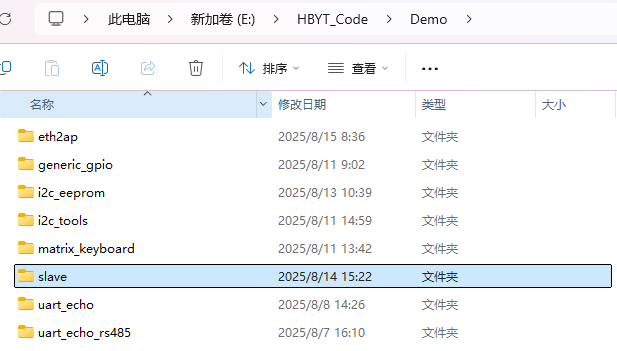
1.3. 进入slave目录
cd slave
1.4. Set the target and start Menuconfig
idf.py set-target esp32c6
idf.py menuconfig
1.5. Navigate and ensure SDIO is enabled. By default it should already be enabled.
Example Configuration
└── Bus Config in between Host and Co-processor
    └── Transport layer
        └── Select "SDIO"
1.6. Build the firmware
idf.py build
1.7. Connect the Program Header on the ESP-Prog to the PROG_C6 header on the board. The connections are as follows:
| ESP-Prog | PROG_C6 | Notes |
|---|---|---|
| ESP_EN | EN | |
| ESP_TXD | TXD | |
| ESP_RXD | RXD | |
| VDD | - | Do not connect |
| GND | GND | |
| ESP_IO0 | IO0 |
1.8. Flashing the firmware
The on-board ESP32-P4 controls the reset signal for the ESP32-C6. To
prevent the P4 interfering with the C6 while flashing (by asserting
the C6 Reset signal during the firmware download), set the P4 into
Bootloader mode before flashing the firmware to the C6:
Manual Way
1. hold down the `BOOT` button on the board
2. press and release the `RST` button on the board
3. release the `BOOT` button
Script Way
esptool.py -p <host_serial_port> --before default_reset --after no_reset run
You can now flash the firmware to the C6 (and monitor the console
output):
idf.py -p <Serial Port> flash monitor
2. ESP32-P4 编译烧录固件
使用 ESP32-P4-Function-EV-Board 开发板。
eth2ap例程(使用ESP-IDF V5.4.1,menuconfig 保持默认,编译烧录运行成功。使用ESP-IDF V5.5.0,编译烧录成功,运行失败,失败原因没有分析)
2.1. Adding Components
Add esp_wifi_remote and esp_hosted components to the project:
idf.py add-dependency "espressif/esp_wifi_remote"
idf.py add-dependency "espressif/esp_hosted"
Remove ‘esp-extconn’ if present in main/idf_component.yml, as esp-extconn and esp-hosted cannot work together.
Open the main/idf_component.yml file and remove/comment the following block if present:
# ------- Delete or comment this block ---------
espressif/esp-extconn:
  version: "~0.1.0"
  rules:
    - if: "target in [esp32p4]"
# -----------------------------------
It is always good to use esp_wifi_remote as it provides all the Wi-Fi config and a wrapper abstraction layer.
But you can also evaluate without using it.
[!IMPORTANT]
Co-processor selection is done by wifi-remote. Ensure the correct
co-processor chip is selected inComponent config->Wi-Fi Remote->choose slave target. The target selected will affect
the ESP-Hosted transport options and default GPIOs used.
2.2. Configuring Defaults
Edit the sdkconfig.defaults.esp32p4 file such that, it would have following content:
#### Comment below two lines if present:
# CONFIG_ESP_HOST_WIFI_ENABLED=y
# CONFIG_PARTITION_TABLE_SINGLE_APP_LARGE=y

#### Add Wi-Fi Remote config for better performance:
CONFIG_ESP_WIFI_STATIC_RX_BUFFER_NUM=16
CONFIG_ESP_WIFI_DYNAMIC_RX_BUFFER_NUM=64
CONFIG_ESP_WIFI_DYNAMIC_TX_BUFFER_NUM=64
CONFIG_ESP_WIFI_AMPDU_TX_ENABLED=y
CONFIG_ESP_WIFI_TX_BA_WIN=32
CONFIG_ESP_WIFI_AMPDU_RX_ENABLED=y
CONFIG_ESP_WIFI_RX_BA_WIN=32

CONFIG_LWIP_TCP_SND_BUF_DEFAULT=65534
CONFIG_LWIP_TCP_WND_DEFAULT=65534
CONFIG_LWIP_TCP_RECVMBOX_SIZE=64
CONFIG_LWIP_UDP_RECVMBOX_SIZE=64
CONFIG_LWIP_TCPIP_RECVMBOX_SIZE=64

CONFIG_LWIP_TCP_SACK_OUT=y
2.3. Building Firmware
Set the ESP32-P4 as the target, build, flash the firmware and
(optionally) monitor ESP32-P4 console output:
idf.py set-target esp32p4
idf.py build
idf.py -p <Serial Port> flash monitor

智能硬件社区聚焦AI智能硬件技术生态,汇聚嵌入式AI、物联网硬件开发者,打造交流分享平台,同步全国赛事资讯、开展 OPC 核心人才招募,助力技术落地与开发者成长。
更多推荐

 33
33 0
0- 0


 已为社区贡献5条内容

所有评论(0)