Day08_单片机-ADC和DMA
模数转换器作用:将模拟信号转化为数字信号模拟信号:连续周期变化的电信号数字信号:离散的以1/0组成的电信号ADC的应用场景:一般用于电路中的电流/电压检测、也使用在各种传感器采集数据后进行传输(温湿度传感器)的转换过程本质是通过四个关键步骤,将。
一、ADC相关概念
ADC(Analog-to-digital converter):模数转换器
作用:将模拟信号转化为数字信号
模拟信号:连续周期变化的电信号
数字信号:离散的以1/0组成的电信号
ADC的应用场景:一般用于电路中的电流/电压检测、也使用在各种传感器采集数据后进行传输(温湿度传感器)
ADC:就是将连续的模拟信号转换为离散的数字信号ADC 的转换过程本质是通过采样->保持->量化->编码四个关键步骤,将连续信号 “离散化” 为数字代码。
ADC的工作流程:
模拟信号就绪→通道采样并保持信号→量化为离散等级→编码为二进制代码→写入数据寄存器→用户读取数字信号”。
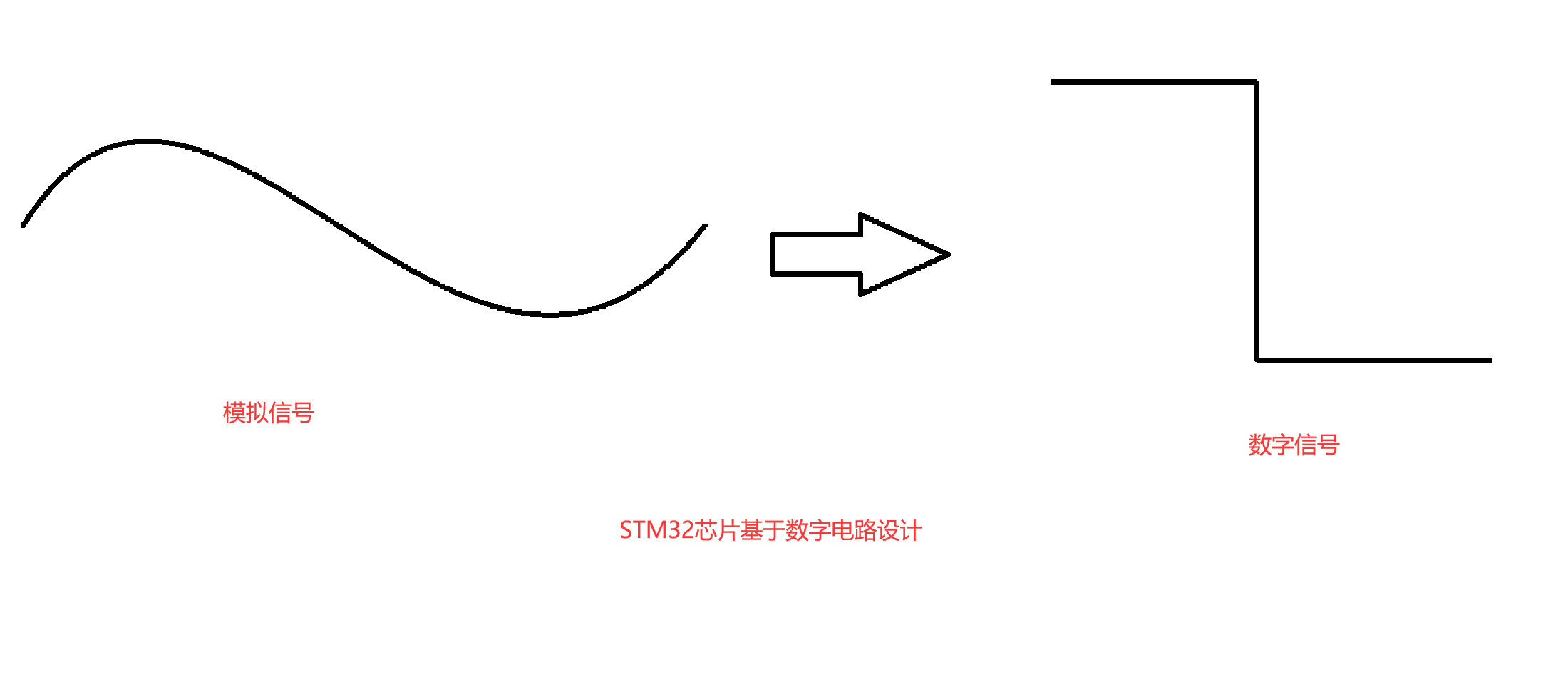
图 1 模拟信号和数字信号
二、ADC1和ADC4
在STM32U575RIT6芯片中支持的是ADC1和ADC4外设控制器
1、采样位数:本质就是采样精度,ADC1采样转化后的数字信号是14位的,ADC4采样转化后的数字信号是12位
2、数据寄存器:采样转化得到的数字信号,会被存储到数据寄存器中,用户只需要读取数据寄存器中的值即可得到转化后的数字信号
3、电压转化公式:请看下图
待测电压=(ADC转化后的数字量*参考电压)/2^采样位数
4、ADC的采样校准和偏移补偿:请看下图
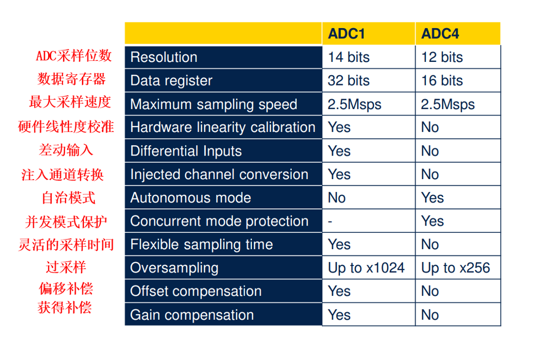
图 2 ADC1 和 ADC4
2.1采样原理
原理图:
图 3 逐次逼近法原理图
ADC 的采样位数:本质是采样精度,是将模拟信号转化为数字信号后的位数;
ADC1 转化后的数字信号是 14 位,ADC4 转化后的数字信号是 12 位
数据寄存器:存储转换后的数字信号
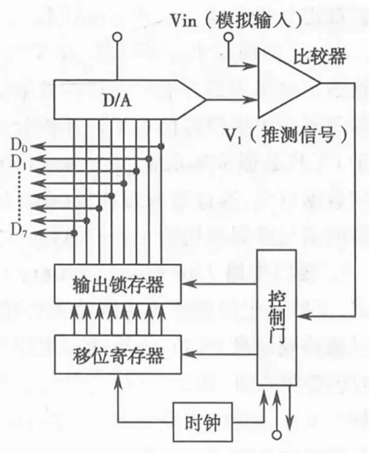
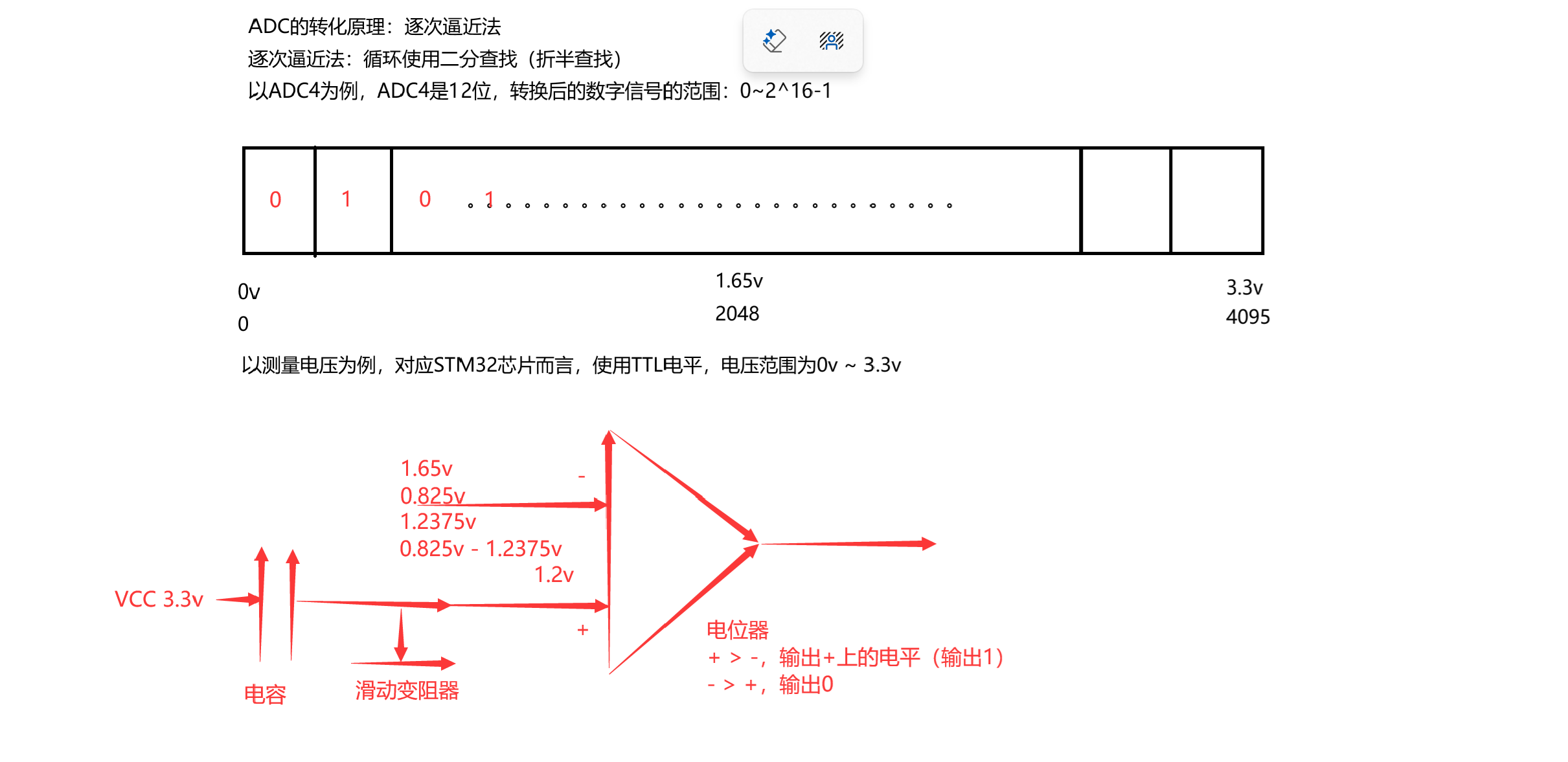
图 4 逐次逼近法原理
解析:
STM32U575RIT6中使用的是ADC采样方式:逐次逼近法。
逐次逼近法:循环使用二分半查找(折半查找)
eg:
以ADC4为例,采样位数为12位,也就是得到的数字信号是12位的(最小是0v最大是3.3v换个思路来理解就是十二位中最小的是0,最大的是4096,中间是1.65v(2048)),现在要查找1.2v(1489)就是一直使用二分缩小范围直到找到他
2.2转换公式
电压转化公式:待测电压(1.2v)、参考电压(3.3v)、ADC转化后的数字量
2^采样位数
ADC转化得到的数字量=------------------- x 待测电压
参考电压
ADC的视线原理是逐次逼近发,但是在使用ADC时,用于只需要打开ADC、等待ADC采样并转化、获取转化后的值就可以了
2.3采样校准和偏移补偿
图:
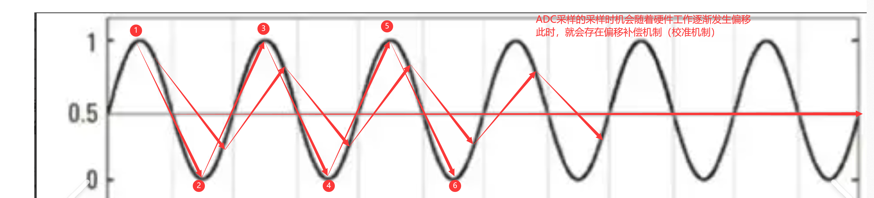
图 5 采样时机和偏移补偿图示
注释:
ADC的采样就相当于录制一个跳舞的视频
一个跳舞的视频=很多跳舞动作的图片,按顺序播放
拍对应跳舞动作的图片的时机=ADC采样的时机拍照的时机不可能固定=ADC采样时机可能发生偏移
如果ADC采样发生偏移,此时采样得到的诗句可能不是很准确,就需要使用硬件提供的偏移补偿机制(校准机制)
使用偏移补偿机制(校准机制)用于初始化采样机制
2.4ADC的通道
1、等待转化的模拟信号
2、ADC的通道:采样等待转化的模拟信号,在此处进行模拟信号转化为数字信号
3、ADC的数据寄存器:用户可以从此处读到转化完毕的数字信号
2.5ADC1的通道
图:
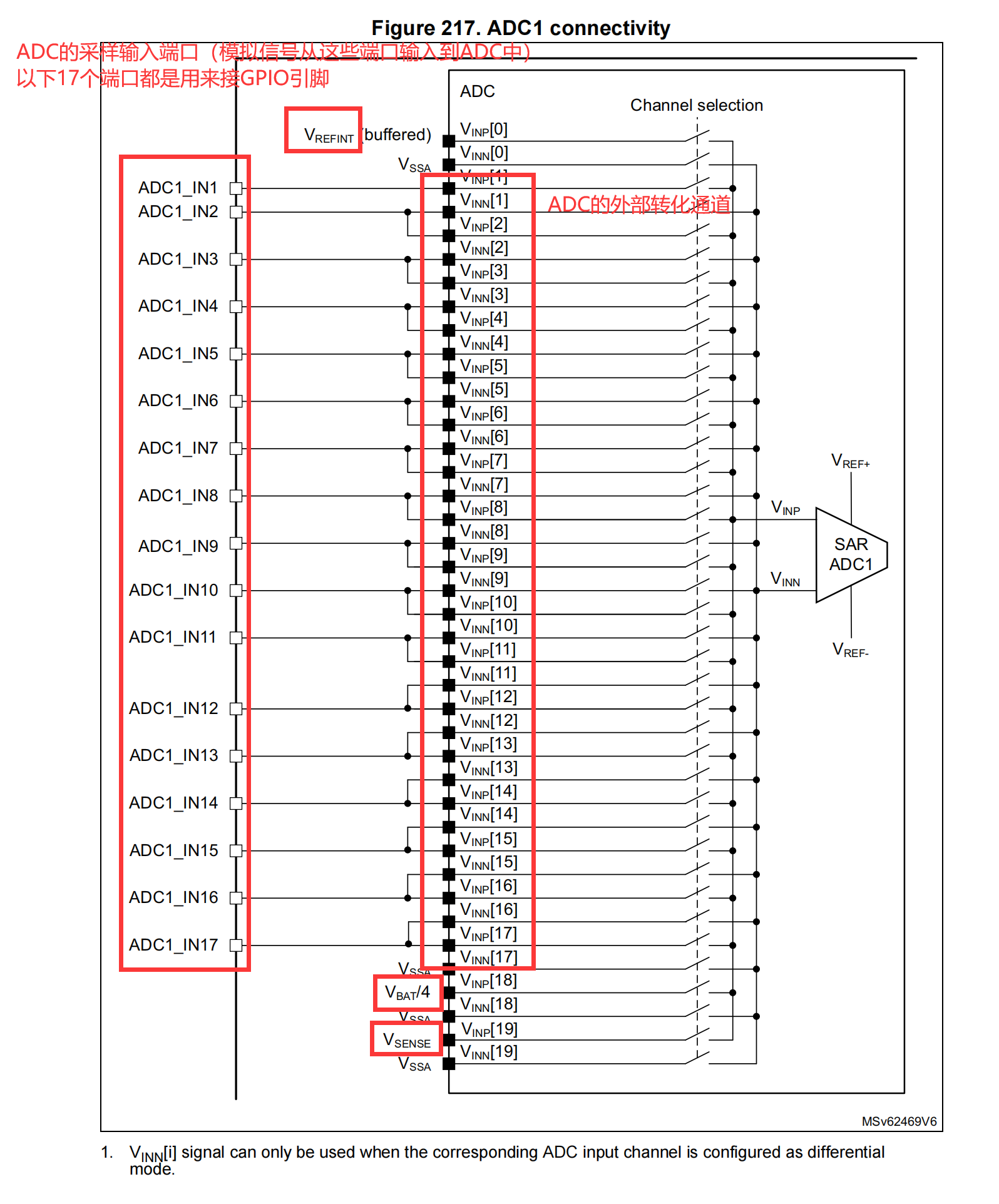
图 6 ADC1 连接图
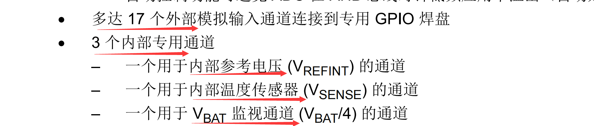
图 7 ADC1 描述
注释:
ADC1:具备20个独立通道(用于采样模拟信号,转化模拟信号)
20个独立通道中:存在17个链接GPIO引脚的通道(外部通道),
存在3个连接芯片内部传感去的通道(内部通道)
2.6ADC4的通道
图:
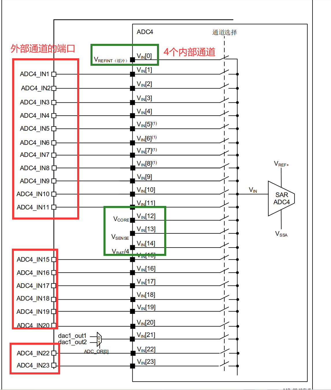
图 8 ADC4 连接图

图 9 ADC4 描述
注释:
ADC4:具备24个独立通道(用于采样模拟信号,转化模拟信号)
24个独立通道中:存在19个链接GPIO引脚的通道(外部通道),
存在4个连接芯片内部传感去的通道(内部通道)
存在1个链接DAC外设控制器的通道
三、ADC的采样转化模式(扫描模式)
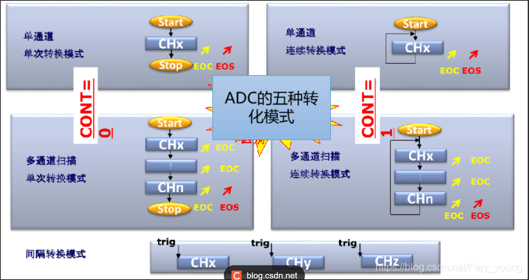
图 10 ADC 的五种采样模式
ADC的采样转化模式有五种:1、单通道单次转化模式 2、单通道连续转化模式 3、多通道单次转化模式 4、多通道连续转化模式 5、间隔转化模式(触发转化模式
1、单通道单次转化模式:
就是只使用一个ADC通道进行模拟信号的采样和转化,并且只转化一次,转化完的数据保存到数据寄存器中,此时当前转化就结束了2、单通道连续转化模式:
使用一个ADC通道进行模拟信号的采样和转化,转化完的数据保存到数据寄存器中,紧接着开启下一次转换
单通道单次转化+while(1)=单通道连续转化
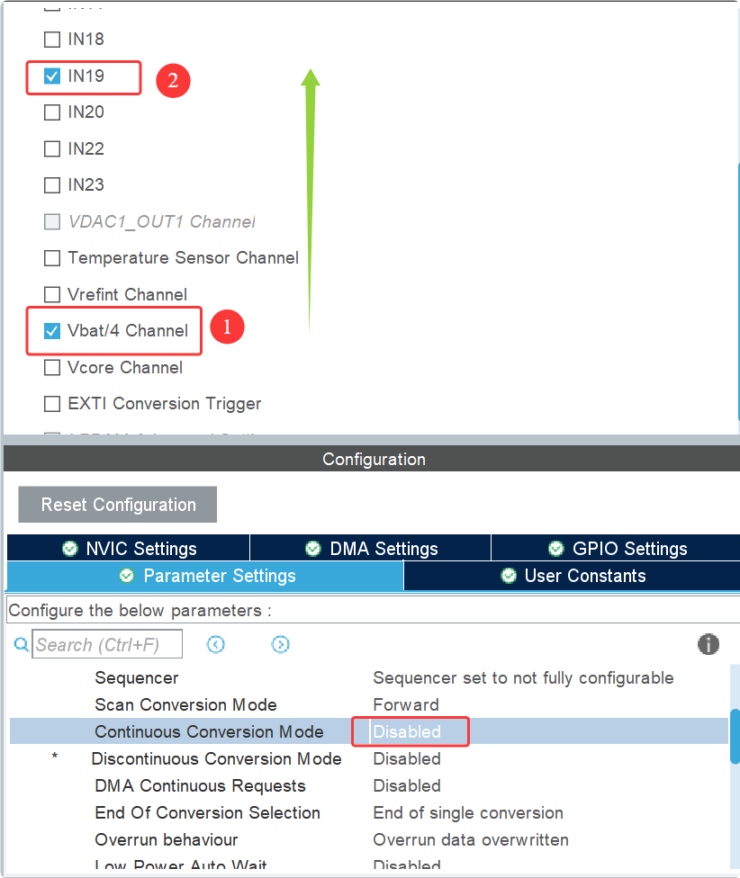
3、多通道单次转化模式:
就是使用多个ADC通道进行模拟信号的采样和转化,按照顺序依次转化通道中的模拟信号,转化完的数据保存到数据寄存器中,当这些使能通道中的数据转化并放到数据寄存器中后,此时当前多通道单次转化就结束了,如果想开次下一次转化,需要手动开启
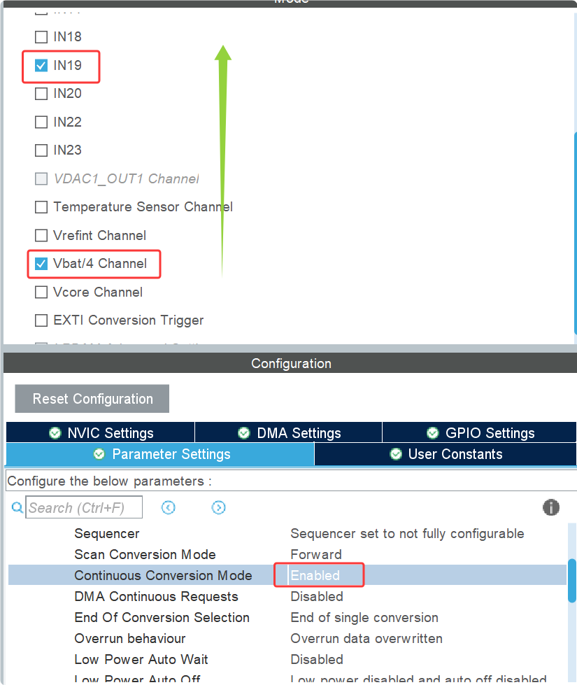
4、多通道连续转化模式:
就是使用多个ADC通道进行模拟信号的采样和转化,按照顺序依次转化通道中的模拟信号,转化完的数据保存到数据寄存器中,当这些使能通道中的数据转化并放到数据寄存器中后,此时会回到最初始的通道开启二次或者N次转化,无需手动开启
多通道单次转化+while(1)=多通道连续转化
5、间隔转化模式(触发转化模式):
使用间隔转化模式时,需要触发源,触发源触发一次,ADC就转化一次ADC的转化模式:独立模式(单通道模式)、扫描模式(多通道模式)、触发模式
四、分析电路图
ANA1->ADC_VDC->PB1
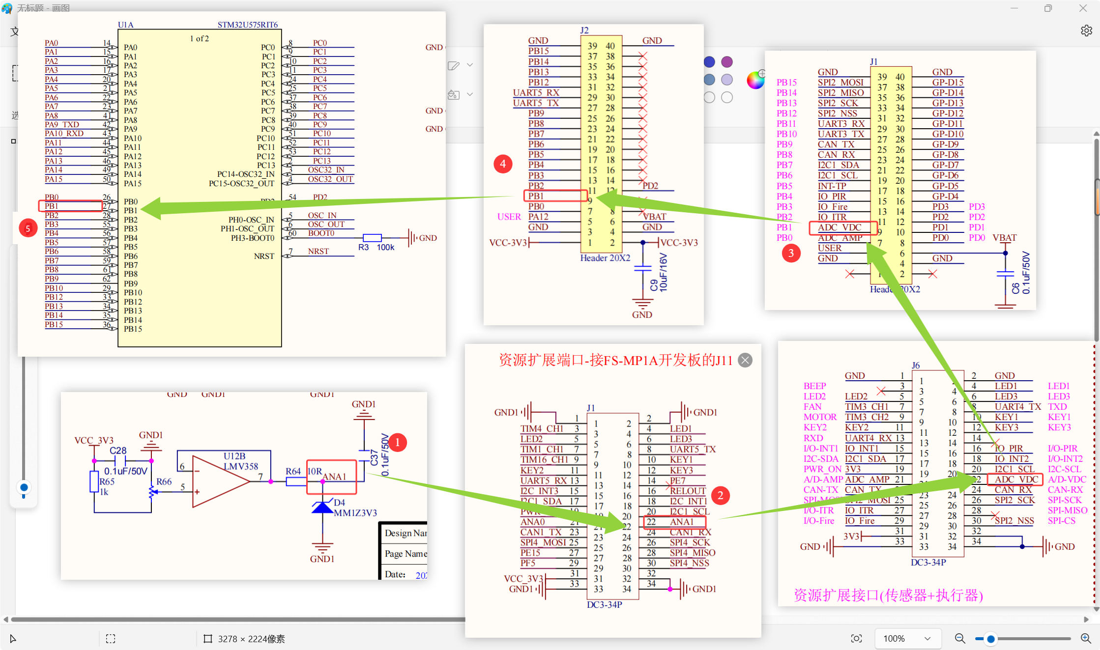
图 11 电路图分析
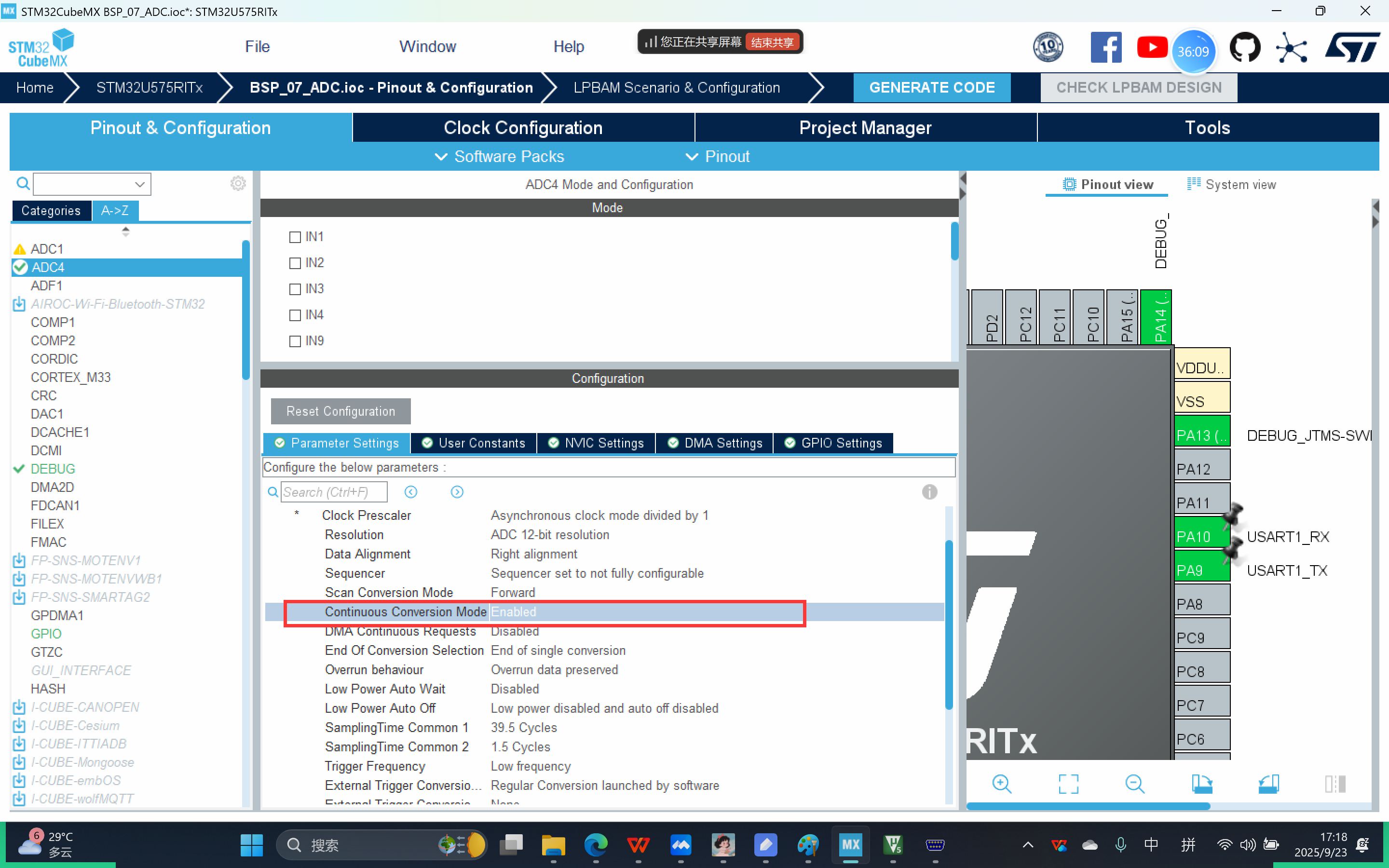
五、CubeMX配置
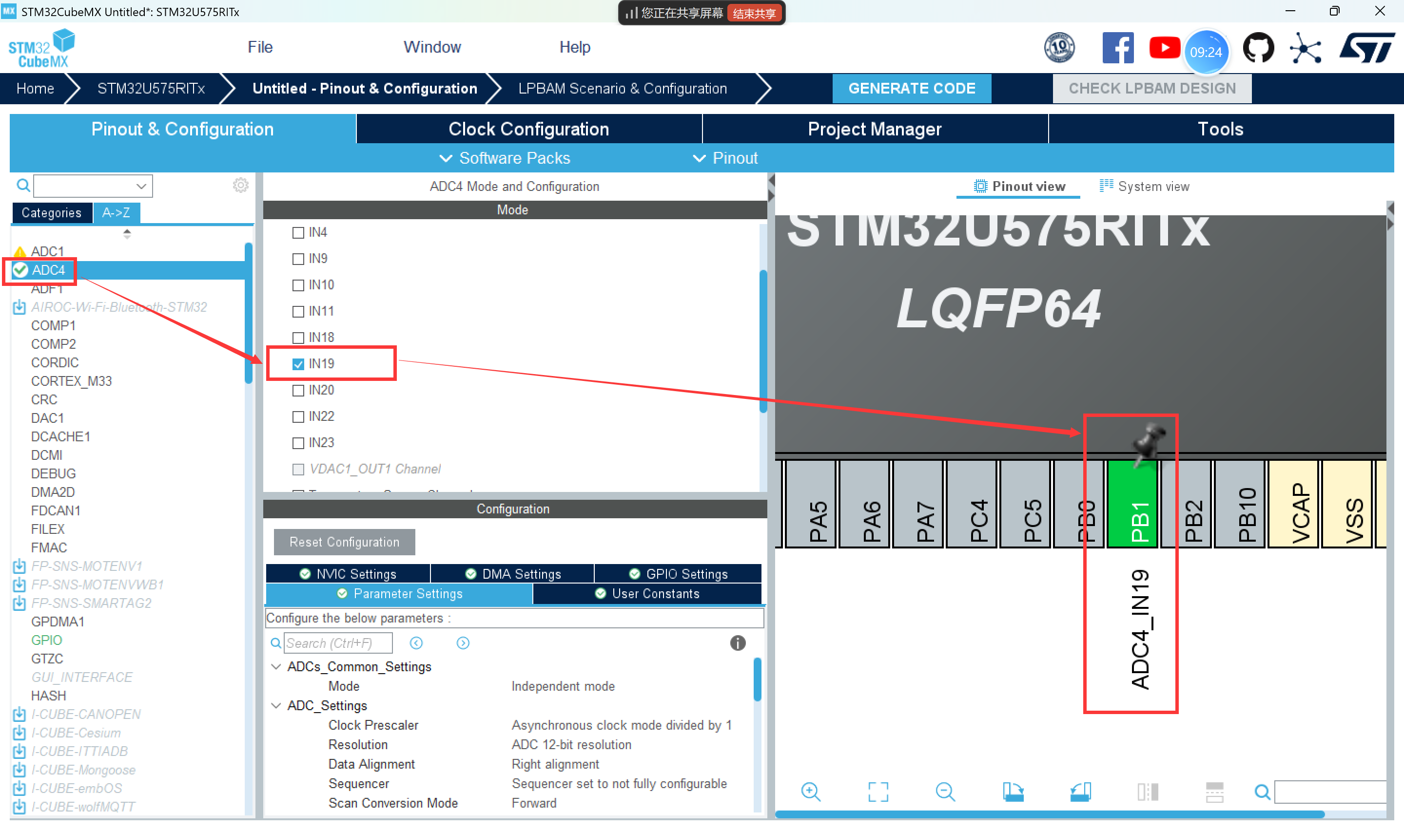
图 12 配置 PB1 引脚为 ADC4_IN19
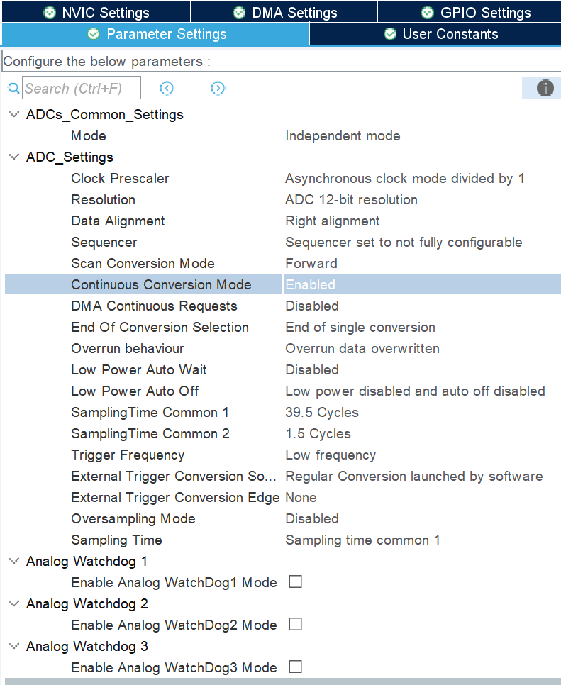
图 13 参数设置
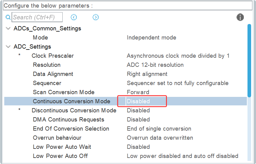
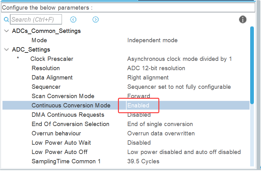
ADCs_Common_Settings(ADC 通用设置)
Mode(模式):Independent mode(独立模式(每个通道都是独立的))
ADC_Settings(ADC 设置)
Clock Prescaler(时钟分频):Asynchronous clock mode divided by 1(时钟分频(时钟频率 -> 影响 ADC 模数转化的速率))
Resolution(采样精度):ADC 12 - bit resolution(采样精度(转化后的数字信号的位数):12 位)
Data Alignment(数据对齐方式):Right alignment(数据对齐方式:右对齐)
Sequencer(序列器):Sequencer set to not fully configurable
Scan Conversion Mode(输入转化模式):Forward(输入转化模式:标准模式(标准转化速率模式))
Continuous Conversion Mode(连续转化模式):Disabled
Discontinuous Conversion Mode(不连续转化模式):Disabled
DMA Continuous Requests(DMA 连续请求):Disabled
End Of Conversion Selection(转换结束选择):End of single conversion
Overrun behaviour(数据保存的机制):Overrun data preserved(数据保存的机制:转化后的数字信号被存储到数据寄存器中可以使用追加 / 覆盖的方式)
Low Power Auto Wait(低功耗自动等待):Disabled
Low Power Auto Off(低功耗自动关闭):Low power disabled and auto off disabled
SamplingTime Common 1(通用采样时间 1):1.5 Cycles(通用的采样时间:1.5 轮转化一次,轮的具体时间需要根据时钟频率来计算 理论上,采样时间越长,采样得到的数据越准确)
SamplingTime Common 2(通用采样时间 2):1.5 Cycles
Trigger Frequency(触发频率):Low frequency
External Trigger Conversion Source(外部触发转换源):Regular Conversion launched by software(使用间隔触发模式时,需要设置)
External Trigger Conversion Edge(外部触发转换沿):None
Oversampling Mode(过采样模式):Disabled
Sampling Time(采样时间):Sampling time common 1(使用采样时间 1)
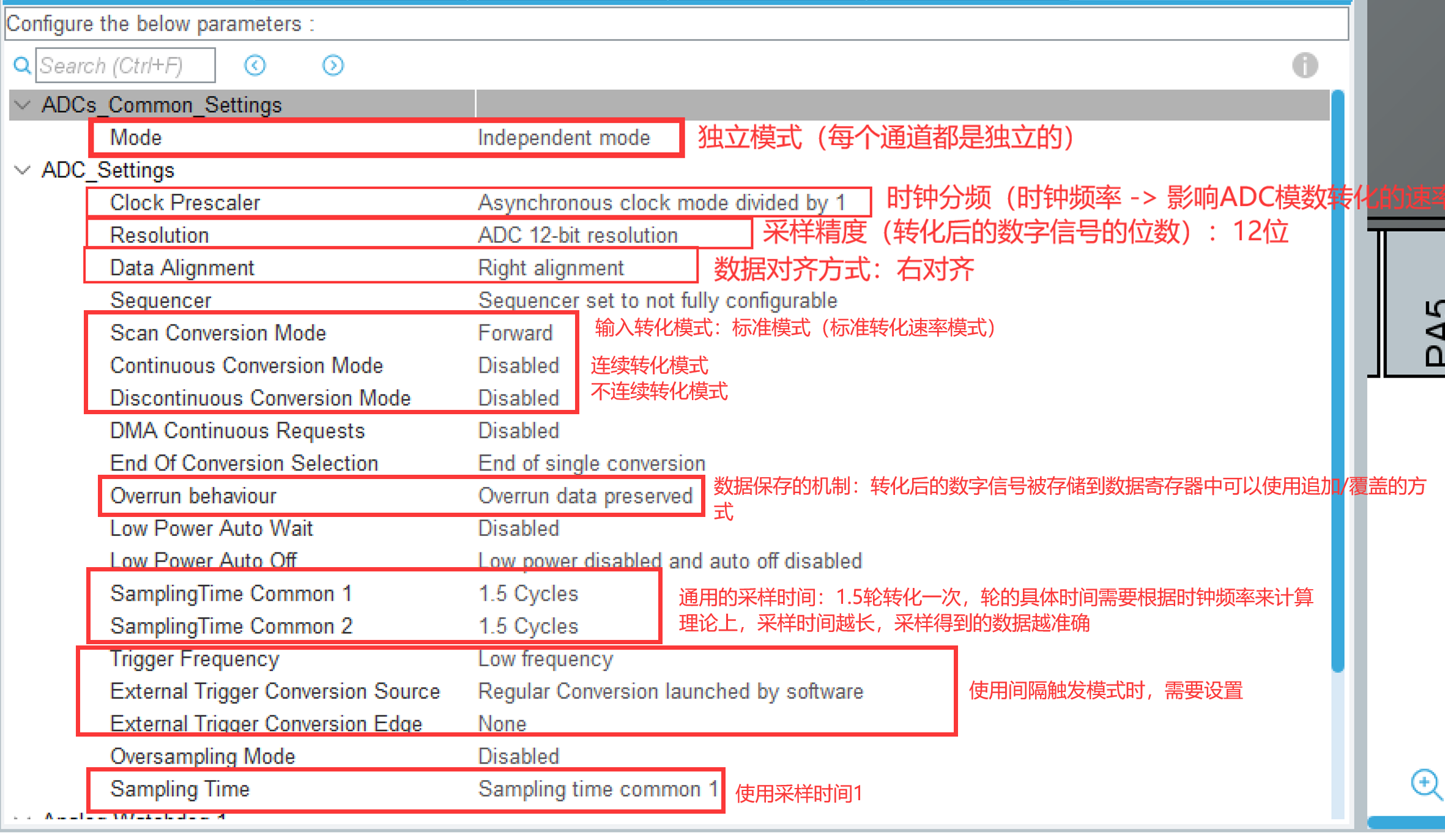
图 14参数设置
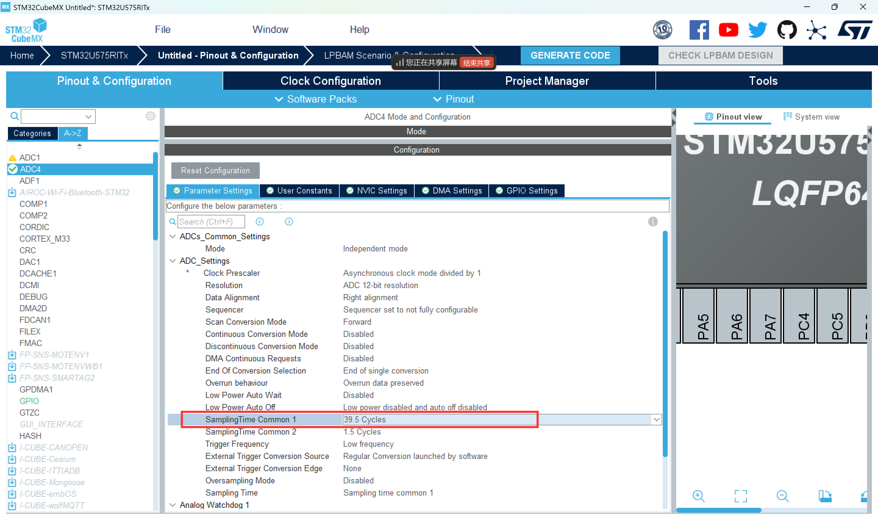
图 15参数设置
图 16参数设置
六、API接口
ADC采样和转化流程:
0、开启ADC采样校准模式1、开启ADC采样转化功能
2、等待采样+转化结束,数字信号被存放到数据寄存器中
3、从数据寄存器中读取数字信号
4、通过模数转化公式,将数字信号转化为模拟信号,并串口打印ADC的采样校准要么在开启采样前,要么在关闭采用后
图 17keil图片01
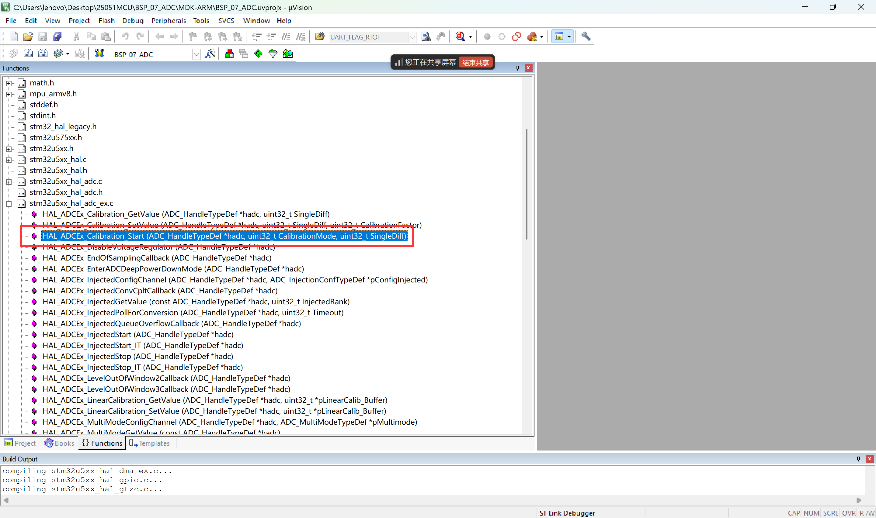
图 18keil图片02
HAL_StatusTypeDef HAL_ADC_Start(ADC_HandleTypeDef *hadc)
功能:
HAL库提供的用于开启ADC采样转化功能的函数
参数:
habc:ADC4外设控制器的句柄
返回值:
函数执行成功,返回HAL_OK
函数返回失败,返回错误码uint32_t HAL_ADC_GetValue(const ADC_HandleTypeDef *hadc)
功能:
HAL库提供的用于获取转化完毕的数字信号的函数
参数:
habc:ADC4外设控制器的句柄
返回值:
返回成功获取的数字信号HAL_StatusTypeDef HAL_ADC_PollForConversion(ADC_HandleTypeDef *hadc,uint32_t Timeout)
功能:
HAL库提供的用于阻塞等待ADC采样+转化完毕,数据被存放到数据寄存器中的函数
参数:
habc:ADC4外设控制器的句柄
Timeout:超时检测时间,当前函数的最大阻塞时间
返回值:
当ADC采样+转化数据完毕后,表示这个函数执行成功,函数执行成功,返回HAL_OK
当ADC采样+转化数据没结束时,此时这个函数处于阻塞状态
函数返回失败,返回错误码#define HAL_MAX_DELAY 0xFFFFFFFU
HAL_StatusTypeDef HAL_ADC_Stop(ADC_HandleTypeDef *hadc)
功能:
HAL库提供的用于关闭ADC采样转化功能的函数
参数:
habc:ADC4外设控制器的句柄
返回值:
函数执行成功,返回HAL_OK
函数返回失败,返回错误码
/**
* @brief Perform an ADC automatic self-calibration
* Calibration prerequisite: ADC must be disabled (execute this
* function before HAL_ADC_Start() or after HAL_ADC_Stop() ).
* @param hadc ADC handle
* @param CalibrationMode Selection of calibration offset or
* linear calibration offset.
* @arg ADC_CALIB_OFFSET Channel in mode calibration offset
* @arg ADC_CALIB_OFFSET_LINEARITY Channel in mode linear calibration offset
* @param SingleDiff Selection of single-ended or differential input
* This parameter can be one of the following values:
* @arg @ref ADC_SINGLE_ENDED Channel in mode input single ended
* @arg @ref ADC_DIFFERENTIAL_ENDED Channel in mode input differential ended
* @retval HAL status
*/
HAL_StatusTypeDef
HAL_ADCEx_Calibration_Start
(ADC_HandleTypeDef *hadc, uint32_t CalibrationMode, uint32_t SingleDiff)功能:
HAL库提供的用于校准ADC采样的函数(此函数只需要开启一次即可)
参数:
hadc:ADC4外设控制器的句柄
CalibrationMode:校准模式的设置
ADC_CALIB_OFFSET 偏移量校准方式(最基础的)
ADC_CALIB_OFFSET_LINEARITY 硬件线性化校准(高级的)
线性化校准比偏移量校准更准确,一般使用一些高精度仪器上
SingleDiff:输入的模拟信号的选择
ADC_SINGLE_ENDED:输入单端信号(一个信号就代表一个电信号)
ADC_DIFFERENTIAL_ENDED:输入差分信号(两个信号代表一个电信号)
返回值:
函数执行成功,返回HAL_OK
函数执行失败,返回错误码
七、代码编写
7.1单通道单次转化模式
/* USER CODE BEGIN Header */
/**
******************************************************************************
* @file : main.c
* @brief : Main program body
******************************************************************************
* @attention
*
* Copyright (c) 2025 STMicroelectronics.
* All rights reserved.
*
* This software is licensed under terms that can be found in the LICENSE file
* in the root directory of this software component.
* If no LICENSE file comes with this software, it is provided AS-IS.
*
******************************************************************************
*/
/* USER CODE END Header */
/* Includes ------------------------------------------------------------------*/
#include "main.h"
#include "adc.h"
#include "usart.h"
#include "gpio.h"
/* Private includes ----------------------------------------------------------*/
/* USER CODE BEGIN Includes */
#include "stdio.h"
/* USER CODE END Includes */
/* Private typedef -----------------------------------------------------------*/
/* USER CODE BEGIN PTD */
/* USER CODE END PTD */
/* Private define ------------------------------------------------------------*/
/* USER CODE BEGIN PD */
/* USER CODE END PD */
/* Private macro -------------------------------------------------------------*/
/* USER CODE BEGIN PM */
/* USER CODE END PM */
/* Private variables ---------------------------------------------------------*/
/* USER CODE BEGIN PV */
/* USER CODE END PV */
/* Private function prototypes -----------------------------------------------*/
void SystemClock_Config(void);
static void SystemPower_Config(void);
/* USER CODE BEGIN PFP */
/* USER CODE END PFP */
/* Private user code ---------------------------------------------------------*/
/* USER CODE BEGIN 0 */
//printf重定向
int fputc(int ch,FILE *stream)
{
HAL_UART_Transmit(&huart1,(uint8_t *)&ch,1,5);
return ch;
}
/* USER CODE END 0 */
/**
* @brief The application entry point.
* @retval int
*/
int main(void)
{
/* USER CODE BEGIN 1 */
/* USER CODE END 1 */
/* MCU Configuration--------------------------------------------------------*/
/* Reset of all peripherals, Initializes the Flash interface and the Systick. */
HAL_Init();
/* USER CODE BEGIN Init */
/* USER CODE END Init */
/* Configure the system clock */
SystemClock_Config();
/* Configure the System Power */
SystemPower_Config();
/* USER CODE BEGIN SysInit */
/* USER CODE END SysInit */
/* Initialize all configured peripherals */
MX_GPIO_Init();
MX_ADC4_Init();
MX_USART1_UART_Init();
/* USER CODE BEGIN 2 */
uint32_t value_digital=0;
//uint32_t value_digital[2]={0};
float value_analog=0;
//stm32u575RIT6需要手动开启VDD电源管理单元的功能
HAL_PWREx_EnableVddA();
HAL_PWREx_EnableVddIO2();
//开启采样ADC4校准
HAL_ADCEx_Calibration_Start(&hadc4,ADC_CALIB_OFFSET,ADC_SINGLE_ENDED);
//HAL_ADC_Start(&hadc4);
//int i=0;
/* USER CODE END 2 */
/* Infinite loop */
/* USER CODE BEGIN WHILE */
while (1)
{
//开启ADC的采样+转化功能
HAL_ADC_Start(&hadc4);
//等待ADC采样+转化完毕
HAL_ADC_PollForConversion(&hadc4,5);
//获取采样完毕的数字信号
value_digital=HAL_ADC_GetValue(&hadc4);
//通过模数转换公式,把获得电压转化为模拟信号
value_analog=value_digital*3.3/4096;
//串口打印
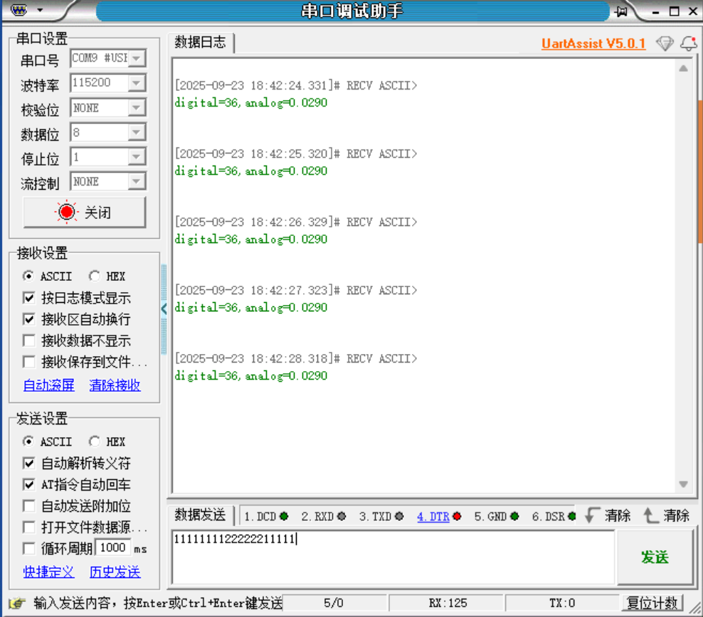
printf("digital=%d,analog=%.4f\n",value_digital,value_analog);
HAL_Delay(1000);
/* USER CODE END WHILE */
/* USER CODE BEGIN 3 */
}
/* USER CODE END 3 */
}
/**
* @brief System Clock Configuration
* @retval None
*/
void SystemClock_Config(void)
{
RCC_OscInitTypeDef RCC_OscInitStruct = {0};
RCC_ClkInitTypeDef RCC_ClkInitStruct = {0};
/** Configure the main internal regulator output voltage
*/
if (HAL_PWREx_ControlVoltageScaling(PWR_REGULATOR_VOLTAGE_SCALE1) != HAL_OK)
{
Error_Handler();
}
/** Initializes the CPU, AHB and APB buses clocks
*/
RCC_OscInitStruct.OscillatorType = RCC_OSCILLATORTYPE_HSI|RCC_OSCILLATORTYPE_MSI;
RCC_OscInitStruct.HSIState = RCC_HSI_ON;
RCC_OscInitStruct.HSICalibrationValue = RCC_HSICALIBRATION_DEFAULT;
RCC_OscInitStruct.MSIState = RCC_MSI_ON;
RCC_OscInitStruct.MSICalibrationValue = RCC_MSICALIBRATION_DEFAULT;
RCC_OscInitStruct.MSIClockRange = RCC_MSIRANGE_0;
RCC_OscInitStruct.PLL.PLLState = RCC_PLL_ON;
RCC_OscInitStruct.PLL.PLLSource = RCC_PLLSOURCE_MSI;
RCC_OscInitStruct.PLL.PLLMBOOST = RCC_PLLMBOOST_DIV4;
RCC_OscInitStruct.PLL.PLLM = 3;
RCC_OscInitStruct.PLL.PLLN = 10;
RCC_OscInitStruct.PLL.PLLP = 2;
RCC_OscInitStruct.PLL.PLLQ = 2;
RCC_OscInitStruct.PLL.PLLR = 1;
RCC_OscInitStruct.PLL.PLLRGE = RCC_PLLVCIRANGE_1;
RCC_OscInitStruct.PLL.PLLFRACN = 0;
if (HAL_RCC_OscConfig(&RCC_OscInitStruct) != HAL_OK)
{
Error_Handler();
}
/** Initializes the CPU, AHB and APB buses clocks
*/
RCC_ClkInitStruct.ClockType = RCC_CLOCKTYPE_HCLK|RCC_CLOCKTYPE_SYSCLK
|RCC_CLOCKTYPE_PCLK1|RCC_CLOCKTYPE_PCLK2
|RCC_CLOCKTYPE_PCLK3;
RCC_ClkInitStruct.SYSCLKSource = RCC_SYSCLKSOURCE_PLLCLK;
RCC_ClkInitStruct.AHBCLKDivider = RCC_SYSCLK_DIV1;
RCC_ClkInitStruct.APB1CLKDivider = RCC_HCLK_DIV1;
RCC_ClkInitStruct.APB2CLKDivider = RCC_HCLK_DIV1;
RCC_ClkInitStruct.APB3CLKDivider = RCC_HCLK_DIV1;
if (HAL_RCC_ClockConfig(&RCC_ClkInitStruct, FLASH_LATENCY_4) != HAL_OK)
{
Error_Handler();
}
}
/**
* @brief Power Configuration
* @retval None
*/
static void SystemPower_Config(void)
{
/*
* Disable the internal Pull-Up in Dead Battery pins of UCPD peripheral
*/
HAL_PWREx_DisableUCPDDeadBattery();
/* USER CODE BEGIN PWR */
/* USER CODE END PWR */
}
/* USER CODE BEGIN 4 */
/* USER CODE END 4 */
/**
* @brief This function is executed in case of error occurrence.
* @retval None
*/
void Error_Handler(void)
{
/* USER CODE BEGIN Error_Handler_Debug */
/* User can add his own implementation to report the HAL error return state */
__disable_irq();
while (1)
{
}
/* USER CODE END Error_Handler_Debug */
}
#ifdef USE_FULL_ASSERT
/**
* @brief Reports the name of the source file and the source line number
* where the assert_param error has occurred.
* @param file: pointer to the source file name
* @param line: assert_param error line source number
* @retval None
*/
void assert_failed(uint8_t *file, uint32_t line)
{
/* USER CODE BEGIN 6 */
/* User can add his own implementation to report the file name and line number,
ex: printf("Wrong parameters value: file %s on line %d\r\n", file, line) */
/* USER CODE END 6 */
}
#endif /* USE_FULL_ASSERT */效果
/* USER CODE BEGIN Header */
/**
  ******************************************************************************
  * @file           : main.c
  * @brief          : Main program body
  ******************************************************************************
  * @attention
  *
  * Copyright (c) 2025 STMicroelectronics.
  * All rights reserved.
  *
  * This software is licensed under terms that can be found in the LICENSE file
  * in the root directory of this software component.
  * If no LICENSE file comes with this software, it is provided AS-IS.
  *
  ******************************************************************************
  */
/* USER CODE END Header */
/* Includes ------------------------------------------------------------------*/
#include "main.h"
#include "adc.h"
#include "usart.h"
#include "gpio.h"

/* Private includes ----------------------------------------------------------*/
/* USER CODE BEGIN Includes */
#include "stdio.h"
/* USER CODE END Includes */

/* Private typedef -----------------------------------------------------------*/
/* USER CODE BEGIN PTD */

/* USER CODE END PTD */

/* Private define ------------------------------------------------------------*/
/* USER CODE BEGIN PD */

/* USER CODE END PD */

/* Private macro -------------------------------------------------------------*/
/* USER CODE BEGIN PM */

/* USER CODE END PM */

/* Private variables ---------------------------------------------------------*/

/* USER CODE BEGIN PV */

/* USER CODE END PV */

/* Private function prototypes -----------------------------------------------*/
void SystemClock_Config(void);
static void SystemPower_Config(void);
/* USER CODE BEGIN PFP */

/* USER CODE END PFP */

/* Private user code ---------------------------------------------------------*/
/* USER CODE BEGIN 0 */
//printf重定向
int fputc(int ch,FILE *stream)
{
	HAL_UART_Transmit(&huart1,(uint8_t *)&ch,1,5);
	return ch;
}
/* USER CODE END 0 */

/**
  * @brief  The application entry point.
  * @retval int
  */
int main(void)
{
  /* USER CODE BEGIN 1 */

  /* USER CODE END 1 */

  /* MCU Configuration--------------------------------------------------------*/

  /* Reset of all peripherals, Initializes the Flash interface and the Systick. */
  HAL_Init();

  /* USER CODE BEGIN Init */

  /* USER CODE END Init */

  /* Configure the system clock */
  SystemClock_Config();

  /* Configure the System Power */
  SystemPower_Config();

  /* USER CODE BEGIN SysInit */

  /* USER CODE END SysInit */

  /* Initialize all configured peripherals */
  MX_GPIO_Init();
  MX_ADC4_Init();
  MX_USART1_UART_Init();
  /* USER CODE BEGIN 2 */
	uint32_t value_digital=0;
	//uint32_t value_digital[2]={0};
	float value_analog=0;
//stm32u575RIT6需要手动开启VDD电源管理单元的功能
	HAL_PWREx_EnableVddA();
	HAL_PWREx_EnableVddIO2();

	//开启采样ADC4校准
	//HAL_ADCEx_Calibration_Start(&hadc4,ADC_CALIB_OFFSET,ADC_SINGLE_ENDED);
	//HAL_ADC_Start(&hadc4);
	//int i=0;
  /* USER CODE END 2 */

  /* Infinite loop */
  /* USER CODE BEGIN WHILE */
  while (1)
  {
		//开启采样ADC4校准
	  HAL_ADCEx_Calibration_Start(&hadc4,ADC_CALIB_OFFSET,ADC_SINGLE_ENDED);
		//开启ADC的采样+转化功能
		HAL_ADC_Start(&hadc4);
		//等待ADC采样+转化完毕
		HAL_ADC_PollForConversion(&hadc4,5);
		//获取采样完毕的数字信号
		value_digital=HAL_ADC_GetValue(&hadc4);
		//通过模数转换公式,把获得电压转化为模拟信号
		value_analog=value_digital*3.3/4096;
		//串口打印
		printf("digital=%d,analog=%.4f\n",value_digital,value_analog);
		HAL_Delay(1000);
    /* USER CODE END WHILE */

    /* USER CODE BEGIN 3 */
  }
  /* USER CODE END 3 */
}

/**
  * @brief System Clock Configuration
  * @retval None
  */
void SystemClock_Config(void)
{
  RCC_OscInitTypeDef RCC_OscInitStruct = {0};
  RCC_ClkInitTypeDef RCC_ClkInitStruct = {0};

  /** Configure the main internal regulator output voltage
  */
  if (HAL_PWREx_ControlVoltageScaling(PWR_REGULATOR_VOLTAGE_SCALE1) != HAL_OK)
  {
    Error_Handler();
  }

  /** Initializes the CPU, AHB and APB buses clocks
  */
  RCC_OscInitStruct.OscillatorType = RCC_OSCILLATORTYPE_HSI|RCC_OSCILLATORTYPE_MSI;
  RCC_OscInitStruct.HSIState = RCC_HSI_ON;
  RCC_OscInitStruct.HSICalibrationValue = RCC_HSICALIBRATION_DEFAULT;
  RCC_OscInitStruct.MSIState = RCC_MSI_ON;
  RCC_OscInitStruct.MSICalibrationValue = RCC_MSICALIBRATION_DEFAULT;
  RCC_OscInitStruct.MSIClockRange = RCC_MSIRANGE_0;
  RCC_OscInitStruct.PLL.PLLState = RCC_PLL_ON;
  RCC_OscInitStruct.PLL.PLLSource = RCC_PLLSOURCE_MSI;
  RCC_OscInitStruct.PLL.PLLMBOOST = RCC_PLLMBOOST_DIV4;
  RCC_OscInitStruct.PLL.PLLM = 3;
  RCC_OscInitStruct.PLL.PLLN = 10;
  RCC_OscInitStruct.PLL.PLLP = 2;
  RCC_OscInitStruct.PLL.PLLQ = 2;
  RCC_OscInitStruct.PLL.PLLR = 1;
  RCC_OscInitStruct.PLL.PLLRGE = RCC_PLLVCIRANGE_1;
  RCC_OscInitStruct.PLL.PLLFRACN = 0;
  if (HAL_RCC_OscConfig(&RCC_OscInitStruct) != HAL_OK)
  {
    Error_Handler();
  }

  /** Initializes the CPU, AHB and APB buses clocks
  */
  RCC_ClkInitStruct.ClockType = RCC_CLOCKTYPE_HCLK|RCC_CLOCKTYPE_SYSCLK
                              |RCC_CLOCKTYPE_PCLK1|RCC_CLOCKTYPE_PCLK2
                              |RCC_CLOCKTYPE_PCLK3;
  RCC_ClkInitStruct.SYSCLKSource = RCC_SYSCLKSOURCE_PLLCLK;
  RCC_ClkInitStruct.AHBCLKDivider = RCC_SYSCLK_DIV1;
  RCC_ClkInitStruct.APB1CLKDivider = RCC_HCLK_DIV1;
  RCC_ClkInitStruct.APB2CLKDivider = RCC_HCLK_DIV1;
  RCC_ClkInitStruct.APB3CLKDivider = RCC_HCLK_DIV1;

  if (HAL_RCC_ClockConfig(&RCC_ClkInitStruct, FLASH_LATENCY_4) != HAL_OK)
  {
    Error_Handler();
  }
}

/**
  * @brief Power Configuration
  * @retval None
  */
static void SystemPower_Config(void)
{

  /*
   * Disable the internal Pull-Up in Dead Battery pins of UCPD peripheral
   */
  HAL_PWREx_DisableUCPDDeadBattery();
/* USER CODE BEGIN PWR */
/* USER CODE END PWR */
}

/* USER CODE BEGIN 4 */

/* USER CODE END 4 */

/**
  * @brief  This function is executed in case of error occurrence.
  * @retval None
  */
void Error_Handler(void)
{
  /* USER CODE BEGIN Error_Handler_Debug */
  /* User can add his own implementation to report the HAL error return state */
  __disable_irq();
  while (1)
  {
  }
  /* USER CODE END Error_Handler_Debug */
}

#ifdef  USE_FULL_ASSERT
/**
  * @brief  Reports the name of the source file and the source line number
  *         where the assert_param error has occurred.
  * @param  file: pointer to the source file name
  * @param  line: assert_param error line source number
  * @retval None
  */
void assert_failed(uint8_t *file, uint32_t line)
{
  /* USER CODE BEGIN 6 */
  /* User can add his own implementation to report the file name and line number,
     ex: printf("Wrong parameters value: file %s on line %d\r\n", file, line) */
  /* USER CODE END 6 */
}
#endif /* USE_FULL_ASSERT */
7.2单通道连续转化模式
/* USER CODE BEGIN Header */
/**
  ******************************************************************************
  * @file           : main.c
  * @brief          : Main program body
  ******************************************************************************
  * @attention
  *
  * Copyright (c) 2025 STMicroelectronics.
  * All rights reserved.
  *
  * This software is licensed under terms that can be found in the LICENSE file
  * in the root directory of this software component.
  * If no LICENSE file comes with this software, it is provided AS-IS.
  *
  ******************************************************************************
  */
/* USER CODE END Header */
/* Includes ------------------------------------------------------------------*/
#include "main.h"
#include "adc.h"
#include "usart.h"
#include "gpio.h"

/* Private includes ----------------------------------------------------------*/
/* USER CODE BEGIN Includes */
#include "stdio.h"
/* USER CODE END Includes */

/* Private typedef -----------------------------------------------------------*/
/* USER CODE BEGIN PTD */

/* USER CODE END PTD */

/* Private define ------------------------------------------------------------*/
/* USER CODE BEGIN PD */

/* USER CODE END PD */

/* Private macro -------------------------------------------------------------*/
/* USER CODE BEGIN PM */

/* USER CODE END PM */

/* Private variables ---------------------------------------------------------*/

/* USER CODE BEGIN PV */

/* USER CODE END PV */

/* Private function prototypes -----------------------------------------------*/
void SystemClock_Config(void);
static void SystemPower_Config(void);
/* USER CODE BEGIN PFP */

/* USER CODE END PFP */

/* Private user code ---------------------------------------------------------*/
/* USER CODE BEGIN 0 */
//printf重定向
int fputc(int ch,FILE *stream)
{
	HAL_UART_Transmit(&huart1,(uint8_t *)&ch,1,5);
	return ch;
}
/* USER CODE END 0 */

/**
  * @brief  The application entry point.
  * @retval int
  */
int main(void)
{
  /* USER CODE BEGIN 1 */

  /* USER CODE END 1 */

  /* MCU Configuration--------------------------------------------------------*/

  /* Reset of all peripherals, Initializes the Flash interface and the Systick. */
  HAL_Init();

  /* USER CODE BEGIN Init */

  /* USER CODE END Init */

  /* Configure the system clock */
  SystemClock_Config();

  /* Configure the System Power */
  SystemPower_Config();

  /* USER CODE BEGIN SysInit */

  /* USER CODE END SysInit */

  /* Initialize all configured peripherals */
  MX_GPIO_Init();
  MX_ADC4_Init();
  MX_USART1_UART_Init();
  /* USER CODE BEGIN 2 */
	uint32_t value_digital=0;
	//uint32_t value_digital[2]={0};
	float value_analog=0;
//stm32u575RIT6需要手动开启VDD电源管理单元的功能
	HAL_PWREx_EnableVddA();
	HAL_PWREx_EnableVddIO2();

	//开启采样ADC4校准
	HAL_ADCEx_Calibration_Start(&hadc4,ADC_CALIB_OFFSET,ADC_SINGLE_ENDED);
	HAL_ADC_Start(&hadc4);//开启ADC连续转化模式后这一行代码只需要执行一次后续的ADC采样和转化会自动执行
	//int i=0;
  /* USER CODE END 2 */

  /* Infinite loop */
  /* USER CODE BEGIN WHILE */
  while (1)
  {
		//开启ADC的采样+转化功能
		//HAL_ADC_Start(&hadc4);
		//等待ADC采样+转化完毕
		HAL_ADC_PollForConversion(&hadc4,5);
		//获取采样完毕的数字信号
		value_digital=HAL_ADC_GetValue(&hadc4);
		//通过模数转换公式,把获得电压转化为模拟信号
		value_analog=value_digital*3.3/4096;
		//串口打印
		printf("digital=%d,analog=%.4f\n",value_digital,value_analog);
		HAL_Delay(1000);
    /* USER CODE END WHILE */

    /* USER CODE BEGIN 3 */
  }
  /* USER CODE END 3 */
}

/**
  * @brief System Clock Configuration
  * @retval None
  */
void SystemClock_Config(void)
{
  RCC_OscInitTypeDef RCC_OscInitStruct = {0};
  RCC_ClkInitTypeDef RCC_ClkInitStruct = {0};

  /** Configure the main internal regulator output voltage
  */
  if (HAL_PWREx_ControlVoltageScaling(PWR_REGULATOR_VOLTAGE_SCALE1) != HAL_OK)
  {
    Error_Handler();
  }

  /** Initializes the CPU, AHB and APB buses clocks
  */
  RCC_OscInitStruct.OscillatorType = RCC_OSCILLATORTYPE_HSI|RCC_OSCILLATORTYPE_MSI;
  RCC_OscInitStruct.HSIState = RCC_HSI_ON;
  RCC_OscInitStruct.HSICalibrationValue = RCC_HSICALIBRATION_DEFAULT;
  RCC_OscInitStruct.MSIState = RCC_MSI_ON;
  RCC_OscInitStruct.MSICalibrationValue = RCC_MSICALIBRATION_DEFAULT;
  RCC_OscInitStruct.MSIClockRange = RCC_MSIRANGE_0;
  RCC_OscInitStruct.PLL.PLLState = RCC_PLL_ON;
  RCC_OscInitStruct.PLL.PLLSource = RCC_PLLSOURCE_MSI;
  RCC_OscInitStruct.PLL.PLLMBOOST = RCC_PLLMBOOST_DIV4;
  RCC_OscInitStruct.PLL.PLLM = 3;
  RCC_OscInitStruct.PLL.PLLN = 10;
  RCC_OscInitStruct.PLL.PLLP = 2;
  RCC_OscInitStruct.PLL.PLLQ = 2;
  RCC_OscInitStruct.PLL.PLLR = 1;
  RCC_OscInitStruct.PLL.PLLRGE = RCC_PLLVCIRANGE_1;
  RCC_OscInitStruct.PLL.PLLFRACN = 0;
  if (HAL_RCC_OscConfig(&RCC_OscInitStruct) != HAL_OK)
  {
    Error_Handler();
  }

  /** Initializes the CPU, AHB and APB buses clocks
  */
  RCC_ClkInitStruct.ClockType = RCC_CLOCKTYPE_HCLK|RCC_CLOCKTYPE_SYSCLK
                              |RCC_CLOCKTYPE_PCLK1|RCC_CLOCKTYPE_PCLK2
                              |RCC_CLOCKTYPE_PCLK3;
  RCC_ClkInitStruct.SYSCLKSource = RCC_SYSCLKSOURCE_PLLCLK;
  RCC_ClkInitStruct.AHBCLKDivider = RCC_SYSCLK_DIV1;
  RCC_ClkInitStruct.APB1CLKDivider = RCC_HCLK_DIV1;
  RCC_ClkInitStruct.APB2CLKDivider = RCC_HCLK_DIV1;
  RCC_ClkInitStruct.APB3CLKDivider = RCC_HCLK_DIV1;

  if (HAL_RCC_ClockConfig(&RCC_ClkInitStruct, FLASH_LATENCY_4) != HAL_OK)
  {
    Error_Handler();
  }
}

/**
  * @brief Power Configuration
  * @retval None
  */
static void SystemPower_Config(void)
{

  /*
   * Disable the internal Pull-Up in Dead Battery pins of UCPD peripheral
   */
  HAL_PWREx_DisableUCPDDeadBattery();
/* USER CODE BEGIN PWR */
/* USER CODE END PWR */
}

/* USER CODE BEGIN 4 */

/* USER CODE END 4 */

/**
  * @brief  This function is executed in case of error occurrence.
  * @retval None
  */
void Error_Handler(void)
{
  /* USER CODE BEGIN Error_Handler_Debug */
  /* User can add his own implementation to report the HAL error return state */
  __disable_irq();
  while (1)
  {
  }
  /* USER CODE END Error_Handler_Debug */
}

#ifdef  USE_FULL_ASSERT
/**
  * @brief  Reports the name of the source file and the source line number
  *         where the assert_param error has occurred.
  * @param  file: pointer to the source file name
  * @param  line: assert_param error line source number
  * @retval None
  */
void assert_failed(uint8_t *file, uint32_t line)
{
  /* USER CODE BEGIN 6 */
  /* User can add his own implementation to report the file name and line number,
     ex: printf("Wrong parameters value: file %s on line %d\r\n", file, line) */
  /* USER CODE END 6 */
}
#endif /* USE_FULL_ASSERT */
7.3多通道单次转换模式
int main(void)
{
/* USER CODE BEGIN 1 */
/* USER CODE END 1 */
/* MCU Configuration--------------------------------------------------------*/
/* Reset of all peripherals, Initializes the Flash interface and the Systick. */
HAL_Init();
/* USER CODE BEGIN Init */
/* USER CODE END Init */
/* Configure the system clock */
SystemClock_Config();
/* Configure the System Power */
SystemPower_Config();
/* USER CODE BEGIN SysInit */
/* USER CODE END SysInit */
/* Initialize all configured peripherals */
MX_GPIO_Init();
MX_ADC4_Init();
MX_USART1_UART_Init();
/* USER CODE BEGIN 2 */
//STM32U575RIT6需要手动开启VDD电源管理单元的功能
HAL_PWREx_EnableVddA();
HAL_PWREx_EnableVddIO2();
HAL_ADCEx_Calibration_Start(&hadc4,ADC_CALIB_OFFSET,ADC_SINGLE_ENDED);
uint32_t buf[2]={0};
float value[2]={0};
//开启ADC转换功能,开启连续转化只需要执行一次开始,后续自动执行
//HAL_ADC_Start(&hadc4);
/* USER CODE END 2 */
/* Infinite loop */
/* USER CODE BEGIN WHILE */
while (1)
{
for(int i=0;i<2;i++)
{
//开启ADC转换功能
HAL_ADC_Start(&hadc4);
//等待采样结束和转化完毕
HAL_ADC_PollForConversion(&hadc4,HAL_MAX_DELAY);
buf[i]=HAL_ADC_GetValue(&hadc4);
value[i]=buf[0]*3.3/4096;
}
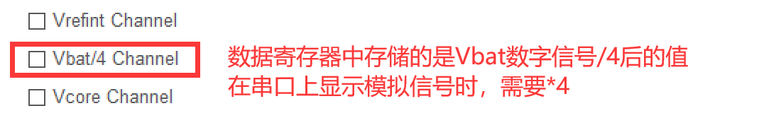
printf("Vbat: digital=%d,analog=%lf\n",buf[0],4*value[0]);
printf("INT9: digital=%d,analog=%lf\n",buf[1],value[1]);
HAL_Delay(1000);
/* USER CODE END WHILE */
/* USER CODE BEGIN 3 */
}
/* USER CODE END 3 */
}/* USER CODE BEGIN Header */
/**
******************************************************************************
* @file : main.c
* @brief : Main program body
******************************************************************************
* @attention
*
* Copyright (c) 2025 STMicroelectronics.
* All rights reserved.
*
* This software is licensed under terms that can be found in the LICENSE file
* in the root directory of this software component.
* If no LICENSE file comes with this software, it is provided AS-IS.
*
******************************************************************************
*/
/* USER CODE END Header */
/* Includes ------------------------------------------------------------------*/
#include "main.h"
#include "adc.h"
#include "usart.h"
#include "gpio.h"
/* Private includes ----------------------------------------------------------*/
/* USER CODE BEGIN Includes */
#include "stdio.h"
/* USER CODE END Includes */
/* Private typedef -----------------------------------------------------------*/
/* USER CODE BEGIN PTD */
/* USER CODE END PTD */
/* Private define ------------------------------------------------------------*/
/* USER CODE BEGIN PD */
/* USER CODE END PD */
/* Private macro -------------------------------------------------------------*/
/* USER CODE BEGIN PM */
/* USER CODE END PM */
/* Private variables ---------------------------------------------------------*/
/* USER CODE BEGIN PV */
/* USER CODE END PV */
/* Private function prototypes -----------------------------------------------*/
void SystemClock_Config(void);
static void SystemPower_Config(void);
/* USER CODE BEGIN PFP */
/* USER CODE END PFP */
/* Private user code ---------------------------------------------------------*/
/* USER CODE BEGIN 0 */
//printf重定向
int fputc(int ch,FILE *stream)
{
HAL_UART_Transmit(&huart1,(uint8_t *)&ch,1,5);
return ch;
}
/* USER CODE END 0 */
/**
* @brief The application entry point.
* @retval int
*/
int main(void)
{
/* USER CODE BEGIN 1 */
/* USER CODE END 1 */
/* MCU Configuration--------------------------------------------------------*/
/* Reset of all peripherals, Initializes the Flash interface and the Systick. */
HAL_Init();
/* USER CODE BEGIN Init */
/* USER CODE END Init */
/* Configure the system clock */
SystemClock_Config();
/* Configure the System Power */
SystemPower_Config();
/* USER CODE BEGIN SysInit */
/* USER CODE END SysInit */
/* Initialize all configured peripherals */
MX_GPIO_Init();
MX_ADC4_Init();
MX_USART1_UART_Init();
/* USER CODE BEGIN 2 */
//uint32_t value_digital=0;
uint32_t value_digital[2]={0};
float value_analog=0;
//stm32u575RIT6需要手动开启VDD电源管理单元的功能
HAL_PWREx_EnableVddA();
HAL_PWREx_EnableVddIO2();
//开启采样ADC4校准
HAL_ADCEx_Calibration_Start(&hadc4,ADC_CALIB_OFFSET,ADC_SINGLE_ENDED);
HAL_ADC_Start(&hadc4);//开启ADC连续转化模式后这一行代码只需要执行一次后续的ADC采样和转化会自动执行
int i=0;
/* USER CODE END 2 */
/* Infinite loop */
/* USER CODE BEGIN WHILE */
while (1)
{
for(i=0;i<2;i++)
{
//等待ADC采样+转化完毕
HAL_ADC_PollForConversion(&hadc4,HAL_MAX_DELAY);
//获取采样完毕的数字信号
value_digital[i]=HAL_ADC_GetValue(&hadc4);
}
printf("%.4f\n",4*value_digital[0]*3.3/4096);
printf("%.4f\n",value_digital[1]*3.3/4096);
HAL_Delay(1000);
/* USER CODE END WHILE */
/* USER CODE BEGIN 3 */
}
/* USER CODE END 3 */
}
/**
* @brief System Clock Configuration
* @retval None
*/
void SystemClock_Config(void)
{
RCC_OscInitTypeDef RCC_OscInitStruct = {0};
RCC_ClkInitTypeDef RCC_ClkInitStruct = {0};
/** Configure the main internal regulator output voltage
*/
if (HAL_PWREx_ControlVoltageScaling(PWR_REGULATOR_VOLTAGE_SCALE1) != HAL_OK)
{
Error_Handler();
}
/** Initializes the CPU, AHB and APB buses clocks
*/
RCC_OscInitStruct.OscillatorType = RCC_OSCILLATORTYPE_HSI|RCC_OSCILLATORTYPE_MSI;
RCC_OscInitStruct.HSIState = RCC_HSI_ON;
RCC_OscInitStruct.HSICalibrationValue = RCC_HSICALIBRATION_DEFAULT;
RCC_OscInitStruct.MSIState = RCC_MSI_ON;
RCC_OscInitStruct.MSICalibrationValue = RCC_MSICALIBRATION_DEFAULT;
RCC_OscInitStruct.MSIClockRange = RCC_MSIRANGE_0;
RCC_OscInitStruct.PLL.PLLState = RCC_PLL_ON;
RCC_OscInitStruct.PLL.PLLSource = RCC_PLLSOURCE_MSI;
RCC_OscInitStruct.PLL.PLLMBOOST = RCC_PLLMBOOST_DIV4;
RCC_OscInitStruct.PLL.PLLM = 3;
RCC_OscInitStruct.PLL.PLLN = 10;
RCC_OscInitStruct.PLL.PLLP = 2;
RCC_OscInitStruct.PLL.PLLQ = 2;
RCC_OscInitStruct.PLL.PLLR = 1;
RCC_OscInitStruct.PLL.PLLRGE = RCC_PLLVCIRANGE_1;
RCC_OscInitStruct.PLL.PLLFRACN = 0;
if (HAL_RCC_OscConfig(&RCC_OscInitStruct) != HAL_OK)
{
Error_Handler();
}
/** Initializes the CPU, AHB and APB buses clocks
*/
RCC_ClkInitStruct.ClockType = RCC_CLOCKTYPE_HCLK|RCC_CLOCKTYPE_SYSCLK
|RCC_CLOCKTYPE_PCLK1|RCC_CLOCKTYPE_PCLK2
|RCC_CLOCKTYPE_PCLK3;
RCC_ClkInitStruct.SYSCLKSource = RCC_SYSCLKSOURCE_PLLCLK;
RCC_ClkInitStruct.AHBCLKDivider = RCC_SYSCLK_DIV1;
RCC_ClkInitStruct.APB1CLKDivider = RCC_HCLK_DIV1;
RCC_ClkInitStruct.APB2CLKDivider = RCC_HCLK_DIV1;
RCC_ClkInitStruct.APB3CLKDivider = RCC_HCLK_DIV1;
if (HAL_RCC_ClockConfig(&RCC_ClkInitStruct, FLASH_LATENCY_4) != HAL_OK)
{
Error_Handler();
}
}
/**
* @brief Power Configuration
* @retval None
*/
static void SystemPower_Config(void)
{
/*
* Disable the internal Pull-Up in Dead Battery pins of UCPD peripheral
*/
HAL_PWREx_DisableUCPDDeadBattery();
/* USER CODE BEGIN PWR */
/* USER CODE END PWR */
}
/* USER CODE BEGIN 4 */
/* USER CODE END 4 */
/**
* @brief This function is executed in case of error occurrence.
* @retval None
*/
void Error_Handler(void)
{
/* USER CODE BEGIN Error_Handler_Debug */
/* User can add his own implementation to report the HAL error return state */
__disable_irq();
while (1)
{
}
/* USER CODE END Error_Handler_Debug */
}
#ifdef USE_FULL_ASSERT
/**
* @brief Reports the name of the source file and the source line number
* where the assert_param error has occurred.
* @param file: pointer to the source file name
* @param line: assert_param error line source number
* @retval None
*/
void assert_failed(uint8_t *file, uint32_t line)
{
/* USER CODE BEGIN 6 */
/* User can add his own implementation to report the file name and line number,
ex: printf("Wrong parameters value: file %s on line %d\r\n", file, line) */
/* USER CODE END 6 */
}
#endif /* USE_FULL_ASSERT */7.4 多通道连续转换模式
int main(void)
{
  /* USER CODE BEGIN 1 */

  /* USER CODE END 1 */

  /* MCU Configuration--------------------------------------------------------*/

  /* Reset of all peripherals, Initializes the Flash interface and the Systick. */
  HAL_Init();

  /* USER CODE BEGIN Init */

  /* USER CODE END Init */

  /* Configure the system clock */
  SystemClock_Config();

  /* Configure the System Power */
  SystemPower_Config();

  /* USER CODE BEGIN SysInit */

  /* USER CODE END SysInit */

  /* Initialize all configured peripherals */
  MX_GPIO_Init();
  MX_ADC4_Init();
  MX_USART1_UART_Init();
  /* USER CODE BEGIN 2 */
	//STM32U575RIT6需要手动开启VDD电源管理单元的功能
	HAL_PWREx_EnableVddA();
	HAL_PWREx_EnableVddIO2();

	HAL_ADCEx_Calibration_Start(&hadc4,ADC_CALIB_OFFSET,ADC_SINGLE_ENDED);

	uint32_t buf[2]={0};
	float value[2]={0};
	//开启ADC转换功能,开启连续转化只需要执行一次开始,后续自动执行
	HAL_ADC_Start(&hadc4);
  /* USER CODE END 2 */

  /* Infinite loop */
  /* USER CODE BEGIN WHILE */
  while (1)
  {
		for(int i=0;i<2;i++)
		{
			//开启ADC转换功能
			//HAL_ADC_Start(&hadc4);
			//等待采样结束和转化完毕
			HAL_ADC_PollForConversion(&hadc4,HAL_MAX_DELAY);

			buf[i]=HAL_ADC_GetValue(&hadc4);
			value[i]=buf[0]*3.3/4096;
		}
		printf("Vbat: digital=%d,analog=%lf\n",buf[0],4*value[0]);
		printf("INT9: digital=%d,analog=%lf\n",buf[1],value[1]);
		HAL_Delay(1000);
    /* USER CODE END WHILE */

    /* USER CODE BEGIN 3 */
  }
  /* USER CODE END 3 */
}
7.5练习:采集Vbat电源电压
八、DMA 相关概念
DMA (General purpose direct memory access controller):通用可编程直接内存访问控制器
内存:广义的内存,包括虚拟内存地址和物理内存地址
DMA 本质是硬件缓冲区(FIFO)
DMA 的作用
减轻 CPU 的压力,将简单的数据存储工作交给 DMA 去做,让 CPU 只负责逻辑处理和数据处理。
DMA 的作用
减轻 CPU 的压力,将简单的数据存储工作交给 DMA 去做,让 CPU 只负责逻辑处理和数据处理。
图 14 DMA 图示
1. GPDMA 支持 16 个独立通道,每个通道都可以用来独立暂存数据
2. GPDMA 的通道用于数据的暂存和传输
单通道传输模式:使用一个通道进行数据传输
多通道传输模式:使用多个通道进行数据传输
同一时刻,只能使用一个 DMA 通道进行数据传输
3. 使用 DMA 通道传输数据前,需要向 DMA 发送使用请求
谁先发送 DMA 通道请求,谁先使用 DMA 通道
4. DMA 通道具有优先级等级,优先级等级高的 DMA 通道线传输数据,分为 4 个等级:
(1)低优先级
(2)中优先级
(3)高优先级
(4)超高优先级
5. 使用 DMA 通道传输数据,一端是 Source 源设备(发送端),一端是 Destination 目标设备(接收端)
6. 使用 DMA 通道传输数据时,有 4 种数据传输方向:
(1)内存 -> 外设
(2)外设 -> 内存
(3)内存 -> 内存
(4)外设 -> 外设 例如:串口的 IDR 寄存器 -> GPIO 的 ODR 寄存器
7. 使用 DMA 通道传输数据时,有数据传输标志位:
(1)数据没有传输完成标志位
(2)数据传输完成一半标志位
(3)数据全部传输完成标志位
8. 使用 DMA 通道传输数据时,可以设置 DMA 通道为不同模式:
(1)标准传输模式 - 内存地址连续时使用
(2)链表传输模式 - 聚集分散模式,物理内存地址不连续时使用
9. 使用 DMA 通道传输数据时,DMA 通道具备的单次最大传输数据范围:
(1)通道 0 - 11 的大小:2 个字 - 8 个字节
(2)通道 12 - 15 的大小:4 个字 - 16 个字节
一般使用 1 / 2 / 4 / 8 个字节为单次传输大小
10. 使用 DMA 通道传输数据时,DMA 内部有两个输出端口(源设备 -> DMA 通道 -> 目标设备)
(1)输出端口 port0
(2)输出端口 port1
源设备发送数据 -> DMA 通道 -> port0 -> 目标设备
注意:源设备和目标设备使用的输出端口必须是同一个
11. 使用 DMA 通道并非将 GPIO 引脚复用为 DMA 的功能,DMA 只是一个缓冲区,使用时只需要将数据放到 DMA 通道中即可
12. DMA 通道的单次传输模式和连续传输模式:
单次传输模式:使用 DMA 通道传输完一次数据后,DMA 通道自动关闭,如果需要继续从 DMA 通道传输数据,需要手动开启 DMA 通道;
连续传输模式:使用 DMA 通道传输完一次数据后,DMA 通道不自动关闭,而回自动继续传输数据。
一般使用连续传输模式,传输完一次完整数据后,手动关闭 DMA 通道
串口的不定长接收 = 串口的接收中断 + 串口的空闲中断
串口的不定长接收 = 串口的 DMA 通道 + 串口的空闲中断
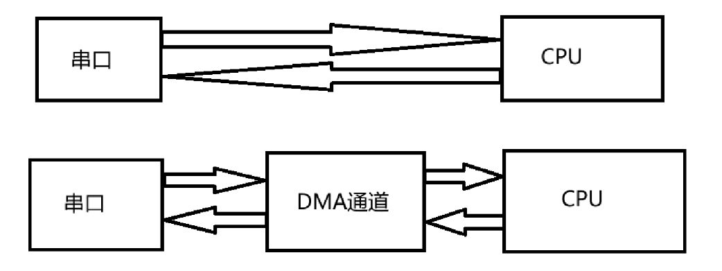
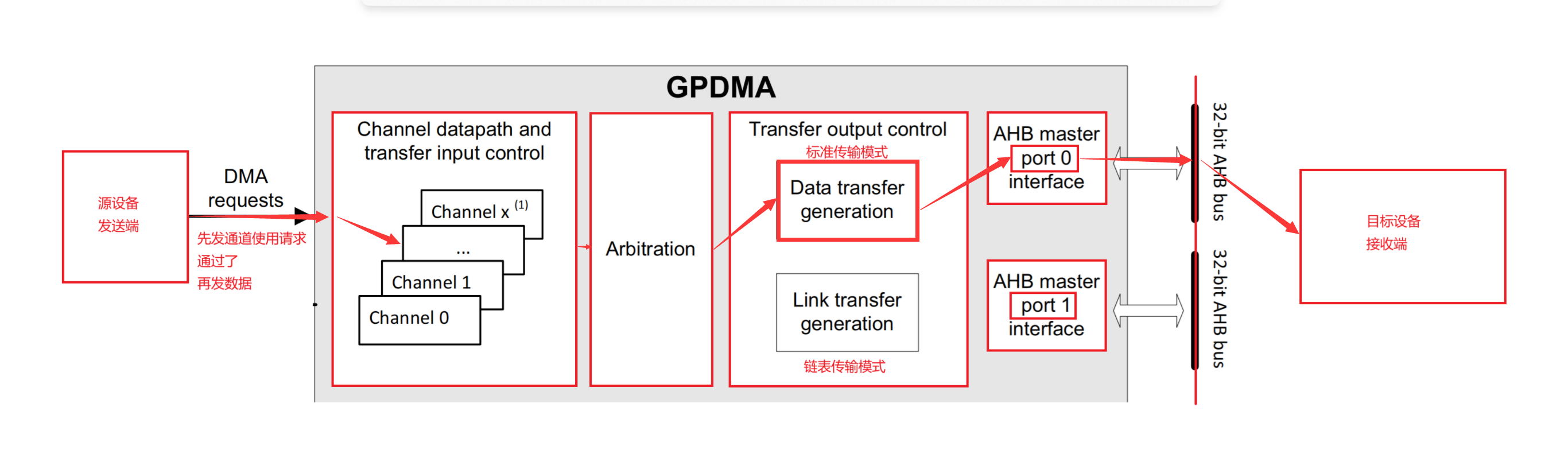
图 15 DMA 内部框图
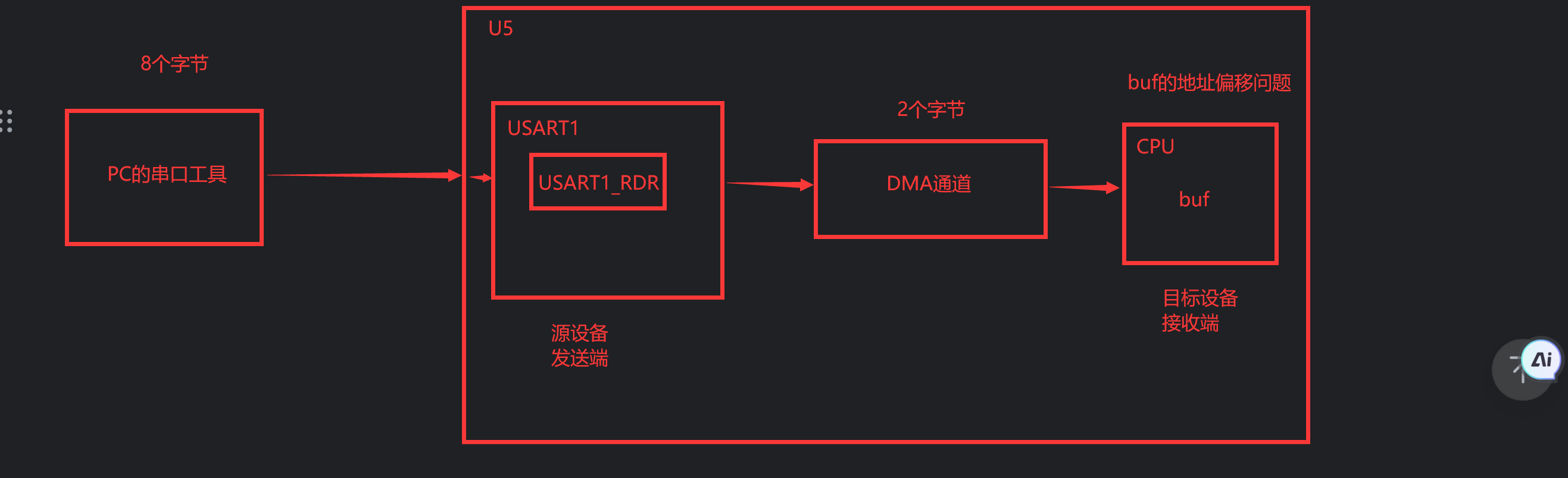
图 16
buf 的地址偏移问题:
DMA 通道从 USART1_RDR 寄存器中读取 1 个字节的数据缓存到 DMA 通道中,再将七写入 buf 中,每次写入前必须将 buf 的地址指针向后偏移 1 个字节才能正确完整存储数据,如果不偏移每次写入会覆盖前一次写入的 1 字节数据;对读取 USART1_RDR 寄存器来说,它的物理地址是固定的,所以对它不用地址偏移。
九、CubeMX 配置
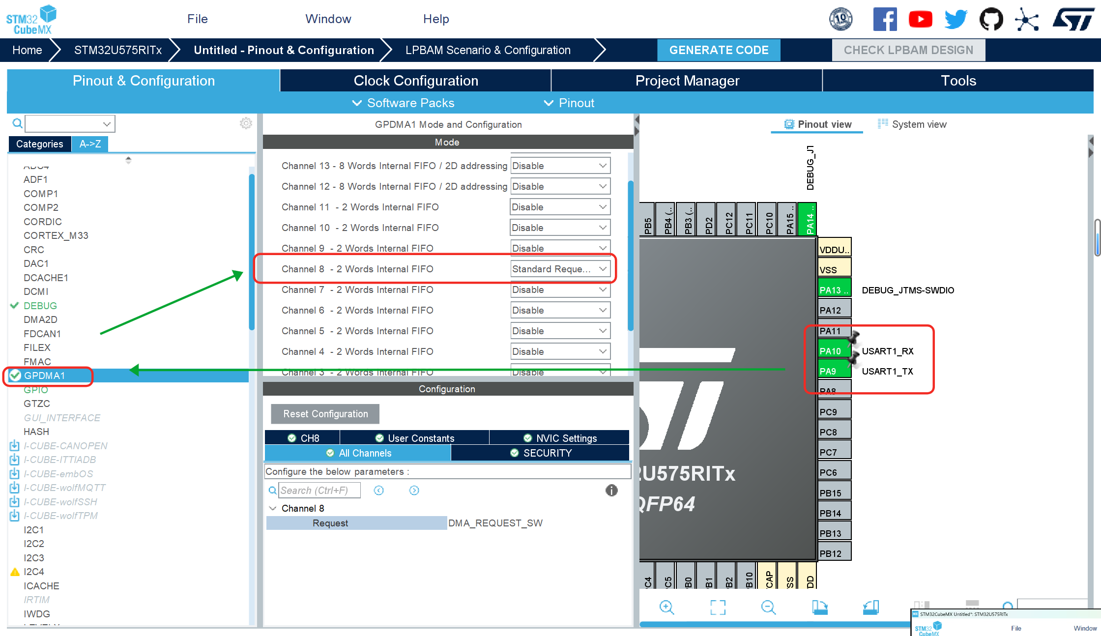
图 17 配置引脚和 DMA 通道使能
配置 USART1 模式,选择 GPDMA 中的 1 个通道并将其设置为 Standard Request Mode.
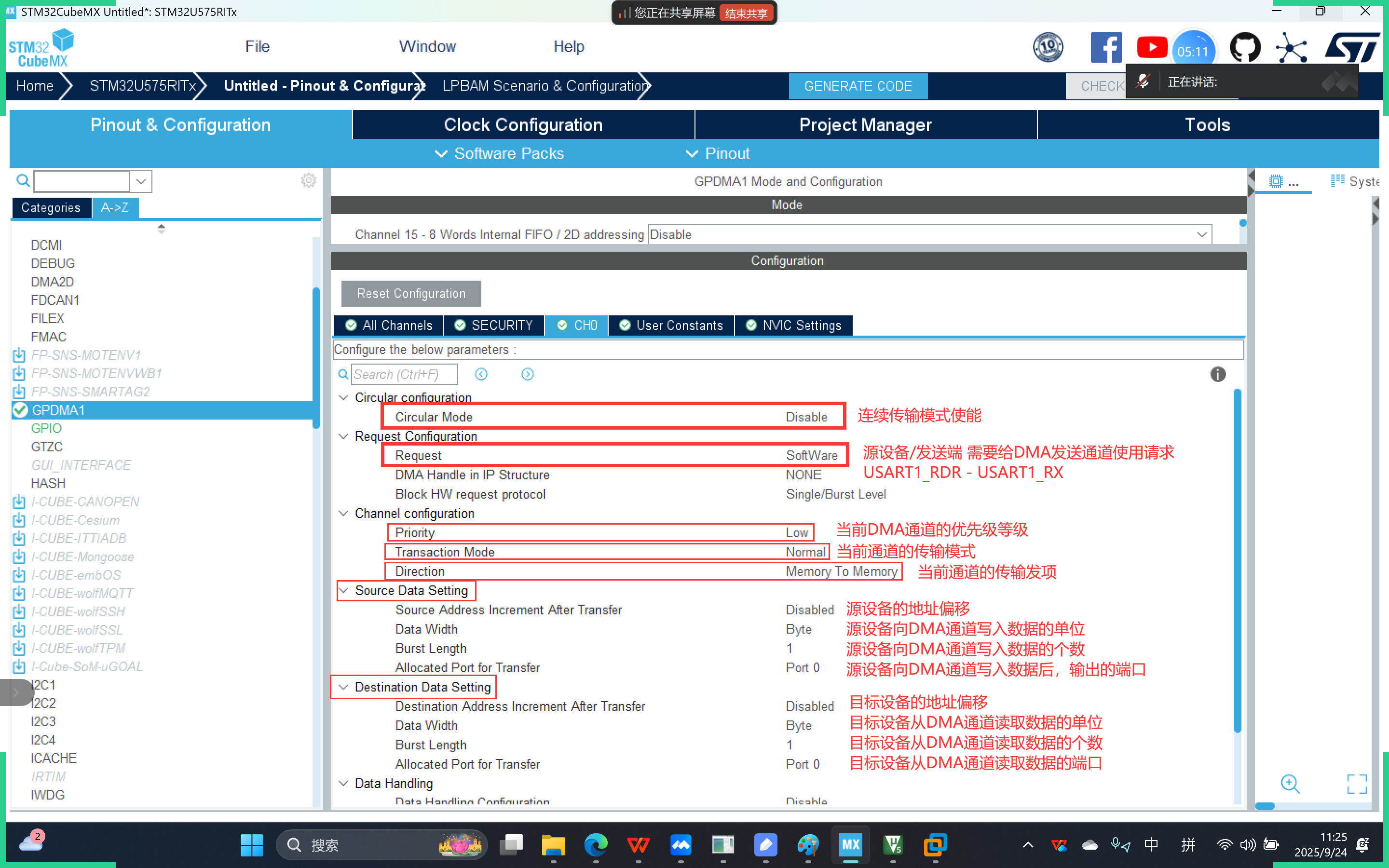
图 18 DMA 一个通道的相关参数
上图是 DMA 其中一个通道的相关参数解释
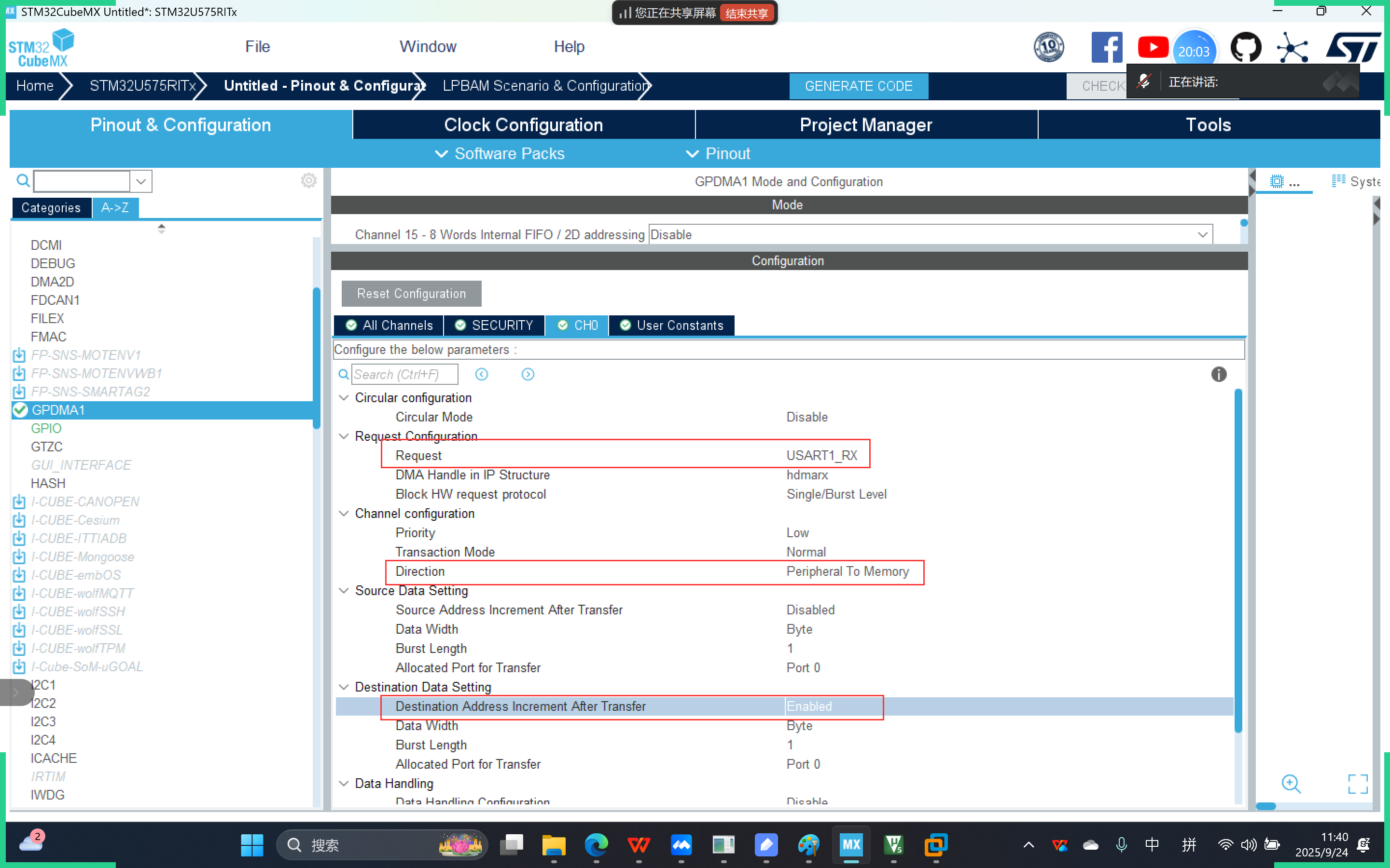
图 19 DMA 通道参数的设置
按照上图一样设置 DMA 通道的参数
地址偏移:
如果从DMA通道读取数据/向DMA通道中写入数据的角色是 连续的内存地址,就需要开启对应的地址偏移
如果从DMA通道读取数据/向DMA通道中写入数据的角色是 固定的物理地址,就不需要开启对应的地址偏移
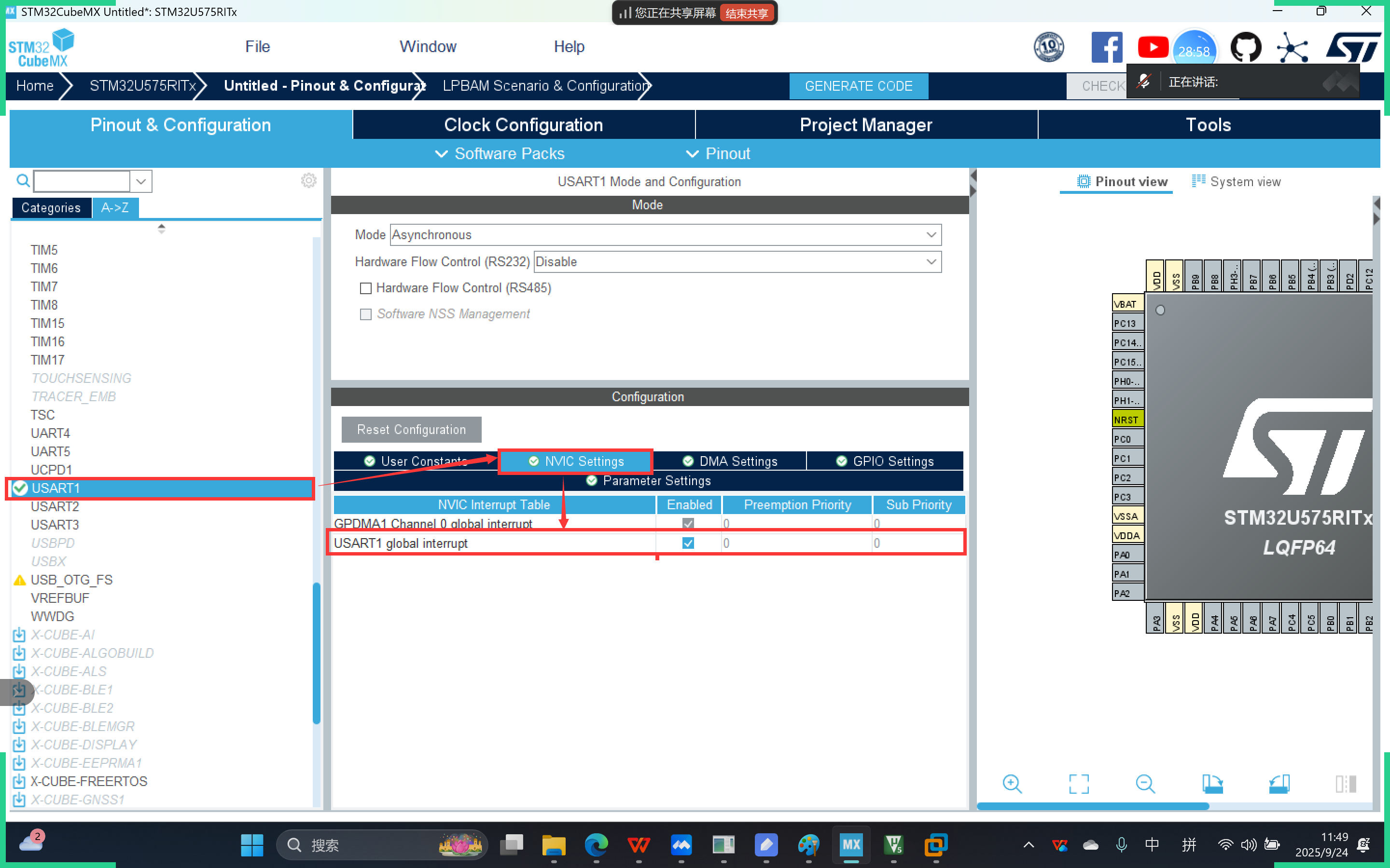
图 20 打开串口的中断使能
打开 USART1 的串口终端使能
十、API 接口
10.1 HAL_UART_Transmit_DMA 函数
HAL_StatusTypeDef HAL_UART_Transmit_DMA(UART_HandleTypeDef *huart, const uint8_t *pData, uint16_t Size)功能:
HAL库提供的用于开启通过DMA通道存储串口接收数据的函数(串口接收到的数据,会被存储到DMA通道中)USART1_RDR -> DMA
参数:
huart:USART1的句柄对象 pData:已经放入到DMA通道中的数据(从DMA通道中读取出来的数据)
Size:需要从DMA通道中读取的数据的大小,单位为字节
返回值:
函数执行成功,返回HAL_OK函数执行失败,返回错误码
10.2 HAL_UART_DMAStop 函数
HAL_StatusTypeDef HAL_UART_DMAStop(UART_HandleTypeDef *huart)功能:
HAL库提供的用于手动关闭串口使用的DMA 在串口使用DMA通道传输完完整数据后,需要手动关闭DMA通道
参数:
huart:USART1的句柄对象返回值:
函数执行成功,返回HAL_OK函数执行失败,返回错误码
十一、代码编写
main.c
/* Private user code ---------------------------------------------------------*/
/* USER CODE BEGIN 0 */
uint8_t buf[1024];
//中断标志
volatile int flag=0;

int fputc(int ch,FILE* stream)
{
	HAL_UART_Transmit(&huart1,(uint8_t*)&ch,1,1);
	return ch;
}
/* USER CODE END 0 */
/* Initialize all configured peripherals */ MX_GPIO_Init(); MX_GPDMA1_Init(); MX_USART1_UART_Init(); /* USER CODE BEGIN 2 */ /* USER CODE END 2 */ //开启串口使用DMA通道接收中断 HAL_UART_Receive_DMA(&huart1,buf,sizeof(buf)); //开启空闲中断 __HAL_UART_ENABLE_IT(&huart1,UART_IT_IDLE); /* Infinite loop */ /* USER CODE BEGIN WHILE */ while (1) { if(flag==1) { printf("buf=%s\n",buf); memset(buf,0,sizeof(buf)); flag=0; } /* USER CODE END WHILE */ /* USER CODE BEGIN 3 */ } /* USER CODE END 3 */ }
stm32u5xx_it.c
void USART1_IRQHandler(void)
{
  /* USER CODE BEGIN USART1_IRQn 0 */
	extern volatile int flag;
	extern uint8_t buf[1024];
  /* USER CODE END USART1_IRQn 0 */
  HAL_UART_IRQHandler(&huart1);
  /* USER CODE BEGIN USART1_IRQn 1 */
	if(__HAL_UART_GET_FLAG(&huart1,UART_FLAG_IDLE))
	{
		__HAL_UART_CLEAR_FLAG(&huart1,UART_CLEAR_IDLEF);

		//手动关闭DMA通道
		HAL_UART_DMAStop(&huart1);

		//逻辑代码
		flag=1;

		//重新开启
		HAL_UART_Receive_DMA(&huart1,buf,sizeof(buf));
	}
  /* USER CODE END USART1_IRQn 1 */
}

智能硬件社区聚焦AI智能硬件技术生态,汇聚嵌入式AI、物联网硬件开发者,打造交流分享平台,同步全国赛事资讯、开展 OPC 核心人才招募,助力技术落地与开发者成长。
更多推荐


 22
22 0
0- 0


 已为社区贡献7条内容

所有评论(0)