Arduino+AD9833测试!DDS
提示:本文内容仅供学习参考。Author: Jonnie Walker CGC
前言
你好! 本文我们将使用AD9833指定输出不同波形的测试过程。从目录中你大概已经知道内容在讲什么了!这里我就不废话了!对于小白建议仔细往下看。
一、AD9833是什么?
AD9833是一种低功耗、可编程波形发生器,能产生正弦、三角形和正方形波形输出。输出频率和相位为软件可编程,允许轻松调整。没有外部组件是必需的。频率寄存器是28位宽:时钟频率为25MHz,分辨率可达0.1 Hz实现;时钟频率为1mhz时,AD9833可调至0.004 Hz分辨率。通过3线串行接口写入AD9833。这个系列接口工作在时钟频率高达40MHz,是兼容DSP和微控制器标准。
......。
主要性能参数:
1.工作电压: 2.3V 至 5.5V (兼容 3.3V 和 5V 系统)
2.输出波形: 正弦波、三角波、方波
3.最大输出频率: 理论上为参考时钟频率的一半(奈奎斯特定律),但实际上受限于内部DAC 的性能,纯净的正弦波输出通常推荐在 0 到 12 MHz。
4.频率分辨率: 28位(取决于频率调谐字的位数),在 25 MHz 时钟下,分辨率约为 0.1 Hz。
5.功耗: 非常低,在 3V 电压下约 5mW,非常适合电池供电设备。
6.控制接口: SPI 兼容的 3 线串行接口。
7.工作温度:−40℃~ +105℃
8.封装: MSOP-10
缺点:
1.输出幅度固定:如果需要调整幅度,需要外接放大器或数字电位器。
2.输出波形纯度:在较高频率时会下降,谐波分量会增加。
3.无法产生任意波形:只能产生内置的三种波形。
二、使用步骤
1.硬件
图1
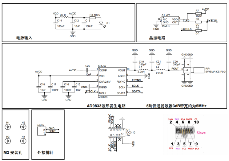
图2
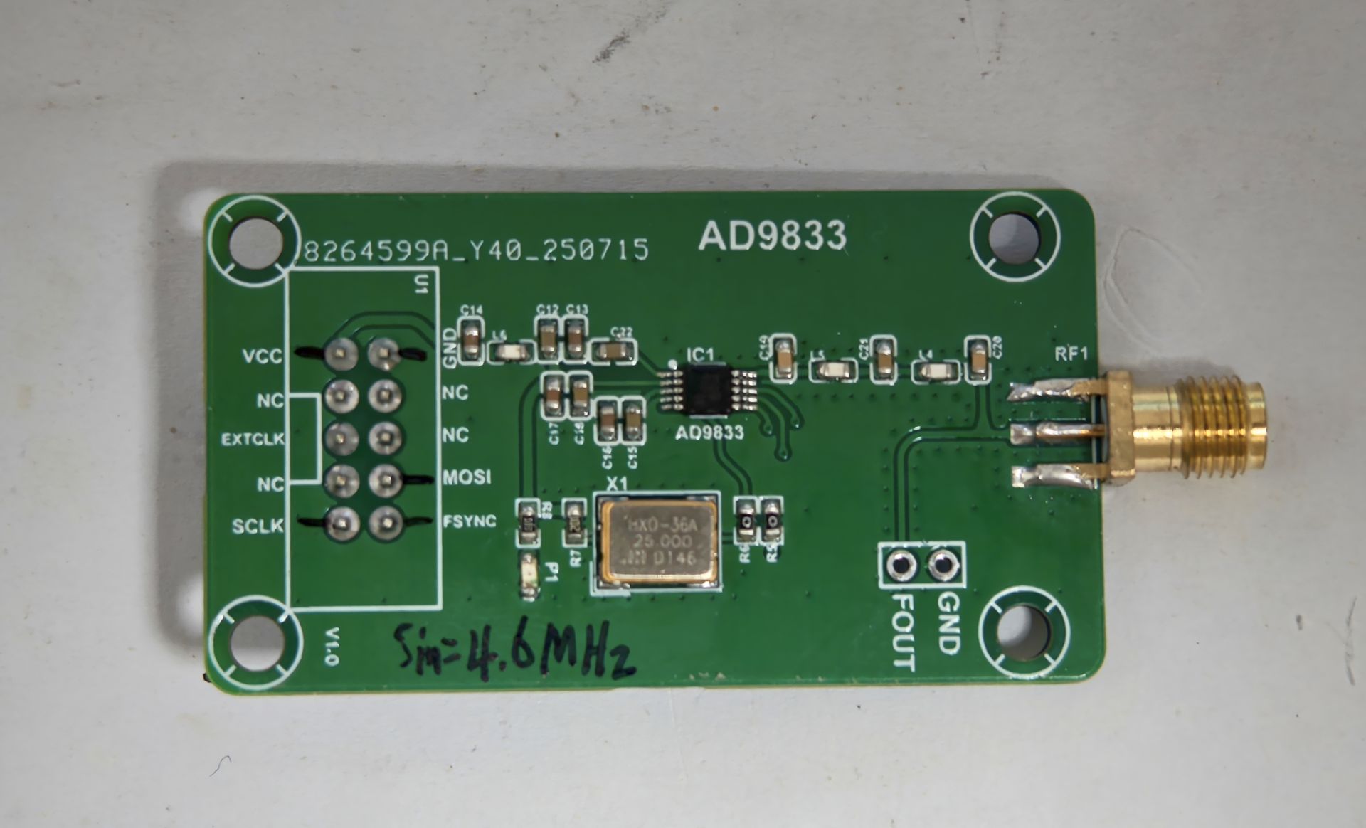
图2为本次测试的实物图,此硬件的带宽5MHz。
硬件通信引脚连接说明:
ArduinoUNO ------------ AD9833
SCK --13 --------------- CLK
MOSI--11 --------------- DAT
PIN4--4 ---------------- FNC
GND ----------------- GND
3.3V-5V ----------------- VCC
图3
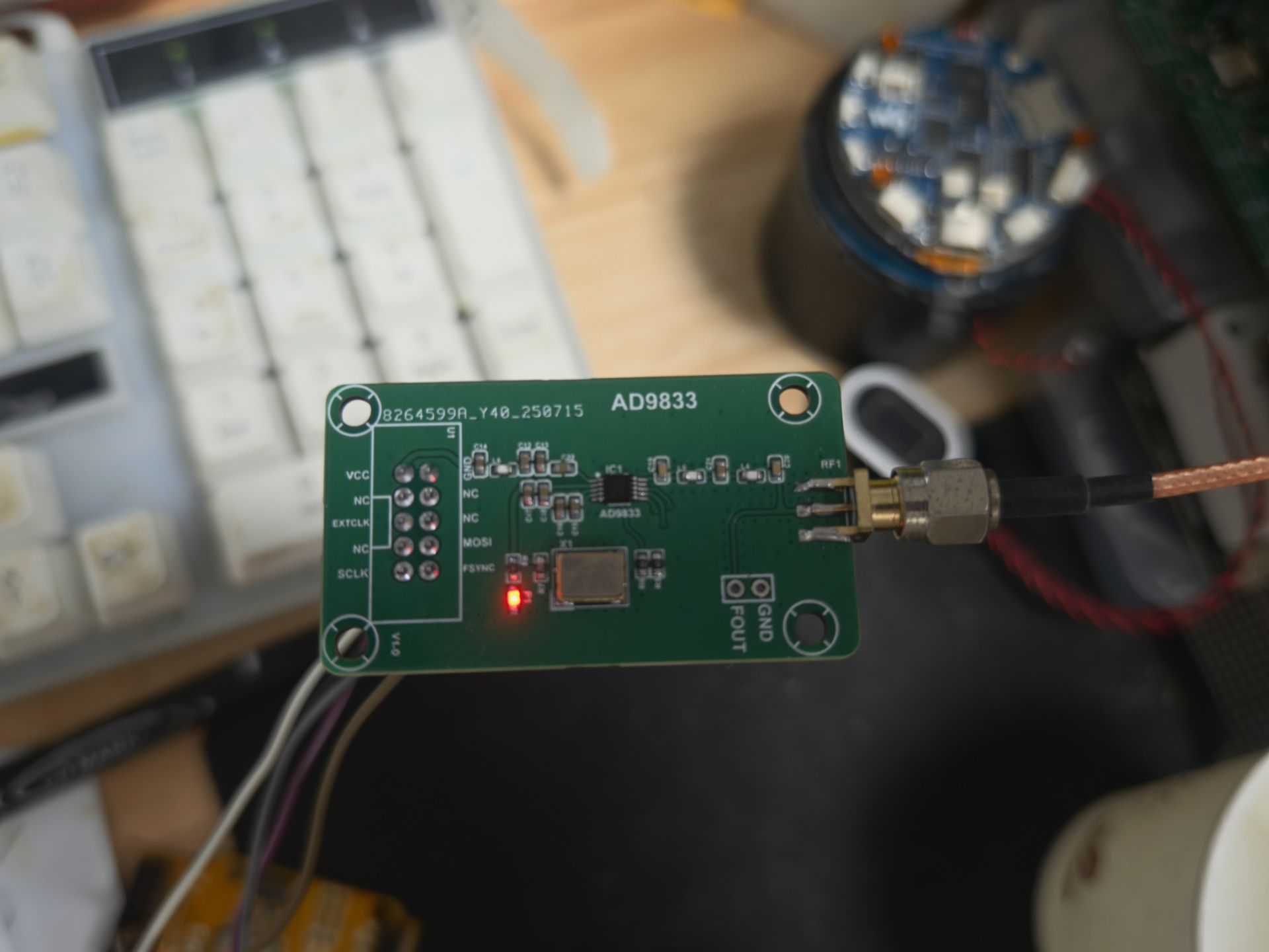
图3为实物测试连接图。
2.软件
测试条件:1.示波器 ,2.AD9833模块(图2)3.Arduino UNO开发板(不固定)
编译环境ArduinoIDE。在编译下面例程时需要安装:AD9833-Library-Arduino-master库文件。
要不然编译出错误!!!!
1.Demo_1
此程序需要结合串口工具,本次使用都是:XCOM V2.0。
比如:自定义频率需要通过串口工具发送5 指令,然后继续发送你需要设定的频率参数比如:1MHz,2MHz,3MHz。
/**
 * @file AD9833_test_suite.ino
 * @author Jonnie Wlaker  CGC
 * @brief  AD9833_Test2
 * @version 0.1
 * @date 2025-10-02
 *
 * @copyright Copyright (c) 2025
 *
 * ------------------------------------------------/
 *
 * 此例程需要结合串口工具,通过串口工具发送简单指令实现不同的功能,具体看一下loop()函数内容。
 * 在程序中我做了注释说明。
 * 在编译前先安装AD9833-Library-Arduino-master库。如果运行功能函数不知道起什么功能,可以去这
 * 个库文件中查看具体封装函数信息!
 *
 *
 */

/*
    ArduinoUNO     AD9833
    -----------------
    SCK --13      CLK
    MOSI--11      DAT
    PIN4--4       FNC
    GND           GND
    3.3V-5V       VCC
 */


#include <AD9833.h>

#define RUNNING       F("\tRUNNING")
#define NOT_RUNNING   F("")
#define ON            F("ON")
#define OFF           F("OFF")
#define LED_PIN       13      // I'm alive blinker
#define FNC_PIN       4       // Any digital pin. Used to enable SPI transfers (active LO

// Some macros to 'improve' readability
#define BLINK_LED         digitalWrite(LED_PIN,millis()%1000 > 500);

/*
 * We need to manually call serialEventRun since we're not returning through the loop()
 * function while inside the test functions. If a character is in the receive buffer,
 * exit the test function. We also blink the I'm Alive LED to give a visual indication
 * that the program is not hung up.
 */
#define YIELD_ON_CHAR     if ( serialEventRun ) serialEventRun(); \
                          if ( Serial.available() ) return; \
                          BLINK_LED

#define DELAY_WITH_YIELD  for ( uint8_t i = 0; i < 10; i++ ) { \
                              YIELD_ON_CHAR \
                              delay(100);   \
                          }

#define FLUSH_SERIAL_INPUT  if ( serialEventRun ) serialEventRun(); \
                            do { Serial.read(); delay(100); } while ( Serial.available() > 0 );

//--------------- Create an AD9833 object ----------------
// Note, SCK and MOSI must be connected to CLK and DAT pins on the AD9833 for SPI
// -----      AD9833 ( FNCpin, referenceFrequency = 25000000UL )
AD9833 gen(FNC_PIN);       // Defaults to 25MHz internal reference frequency

void setup() {
    pinMode(LED_PIN,OUTPUT);

    while (!Serial);          // Delay until terminal opens
    Serial.begin(9600);

    // This MUST be the first command after declaring the AD9833 object
    gen.Begin();              // The loaded defaults are 1000 Hz SINE_WAVE using REG0
                              // The output is OFF, Sleep mode is disabled
    gen.EnableOutput(false);  // Turn ON the output

    PrintMenu(0,true);        // Display menu for the first time
}

void loop() {
    static bool outputOn = false;

    BLINK_LED

    if ( Serial.available() ) {
        char ch = Serial.read();

        FLUSH_SERIAL_INPUT

        PrintMenu(ch,outputOn);
        //通过串口工具发送数据,控制一下功能!
        switch ( ch ) {
            case '1':
                IncrementFrequencyTest();  //将选择的频率寄存器增加freqIncHz
                break;
            case '2':
                CycleWaveformsTest();  //波形切换实现,循环切换所有波形类型
                break;
            case '3':
                SwitchFrequencyRegisterTest();
                break;
            case '4':
                PhaseTest();
                break;
            case '5':
                RequestedvsProgrammedValues(); //设置自定义频率
                break;
            case '6':
                outputOn = ! outputOn;   //开启/关闭输出
                gen.EnableOutput(outputOn);    // Turn off output
                break;
            default:
                Serial.println(F("*** Invalid command ***"));
                break;
        }
    }
}

/*
 * Setup a manual ramp from a Start frequency to a Stop frequency in some increment
 * over a ramp time.
 */
void IncrementFrequencyTest ( void ) {

    float startHz = 1000, stopHz = 5000, incHz = 1, sweepTimeSec = 5.0;

    // Calculate the delay between each increment.
    uint16_t numMsecPerStep = (sweepTimeSec * 1000.0) / ((uint16_t)((stopHz - startHz) / incHz) + 1);
    if ( numMsecPerStep == 0 ) numMsecPerStep = 1;

    // Apply a signal to the output. If phaseReg is not supplied, then
    // a phase of 0.0 is applied to the same register as freqReg
    gen.ApplySignal(SINE_WAVE,REG1,startHz);

    while ( true ) {

        gen.SetFrequency(REG1,startHz-incHz);

        for ( float i = startHz ; i <= stopHz; i += incHz ) {
            YIELD_ON_CHAR
            gen.IncrementFrequency(REG1,incHz);
            delay(numMsecPerStep);
        }
    }
}

/*
 * Cycle through all of the waveform types. Also cycle the
 * frequency registers.
 */
void CycleWaveformsTest ( void ) {

    WaveformType waveType = SINE_WAVE;
     // 设置两个寄存器为相同波形
    gen.SetFrequency(REG0,10000.0);   // Load values
    gen.SetFrequency(REG1,1000.0);
    // We don't care about phase for this test

    while ( true ) {

        gen.SetWaveform(REG1,waveType);   // Next waveform  , 设置波形类型(核心函数)
        gen.SetWaveform(REG0,waveType);
        gen.SetOutputSource(REG1);        // Output 1000 Hz waveform

        // Hack to allow I'm alive lamp a chance to blink and give a better
        // response to user input
        DELAY_WITH_YIELD

        gen.SetOutputSource(REG0);        // Output 10000 Hz waveform

        DELAY_WITH_YIELD

        // 切换波形类型
        switch ( waveType ) {             // Cycle through all the waveform types
            case SINE_WAVE:
                waveType = TRIANGLE_WAVE;
                break;
            case TRIANGLE_WAVE:
                waveType = SQUARE_WAVE;
                break;
            case SQUARE_WAVE:
                waveType = HALF_SQUARE_WAVE;
                break;
            case HALF_SQUARE_WAVE:
                waveType = SINE_WAVE;
                break;
        }
    }
}

/*
 * Fast switching example.
 * I use the FFT display capability on my scope
 */
void SwitchFrequencyRegisterTest ( void ) {

    gen.ApplySignal(SINE_WAVE,REG0,500000);
    gen.ApplySignal(SINE_WAVE,REG1,100000);
    gen.SetPhase(REG1,180);           // Offset second freq by 180 deg
    gen.Reset();

    while ( true ) {                  // This takes time

        YIELD_ON_CHAR                 // This takes more time

        gen.SetOutputSource(REG0);    // This takes about 18 usec
        gen.SetOutputSource(REG1);    // This takes about 18 usec

        // What ends up is REG0 frequency is active a shorter amount of time
        // then REG1 frequency. In the sepctrum, the duty cycle differences will
        // show up (power is lower by 10log(DC))
    }
}

/*
 * Phase shift between REG0 and REG1. Use a oscilloscope set to Normal
 * triggering, AC coupling, 500usec/div, 100 mV/div. This will display
 * about two cycles for register 0, 4 cycle for register 1, plus dead
 * time for the Reset.
 * Use Normal triggering so the display remains even when triggering is
 * lost. Can use any waveform for this test. Remember that the square
 * wave is about 5v-pp while sine and triangle are about 600 mv-pp
 */
void PhaseTest ( void ) {

    gen.ApplySignal(TRIANGLE_WAVE,REG0,1000);
    gen.ApplySignal(SINE_WAVE,REG1,2000);

    bool reverse = true;

    while ( true ) {
        reverse = ! reverse;

        for ( int16_t i = 0; i <= 360; i += 1 ) {
            if ( ! reverse )
                gen.IncrementPhase(REG1,-1);
            else
                gen.IncrementPhase(REG1,1);

            YIELD_ON_CHAR
            /*
             * Display ~ 2 cycles using REG0 phase. If no REG is supplied for phase,
             * defaults to REG specified for frequency. RESET is removed during this
             * function call.
             */
            gen.SetOutputSource(REG0);
            /*
             * This is just a wag to try to get exactly 2 cycles of the waveform.
             * It makes the phase alignments easier to verify.
             */
            delayMicroseconds(1900);

            YIELD_ON_CHAR

            /* This also works if you keep using REG1 for frequency
             * Now display ~ 4 cycles using REG1
             */
            gen.SetOutputSource(REG1);
            delayMicroseconds(1950);
            /*
             * Turn off for remaining trace. Reset the registers so triggering occurs
             * on the start of REG0 signal. Reset() includes 15 msec delay which is good
             * to ensure sweep is completed.
             * I tried using EnableOutput(true) then EnableOutput(false) in this
             * loop but could not get reliable triggering on the scope.
             *
             * The difference between Reset() and EnableOutput(false) is that EnableOutput(false)
             * keeps the AD9833 in RESET until you specifically remove the RESET using
             * EnableOutput(true). However, after a call to Reset(), calls to ANY function
             * EXCEPT Set/Increment Phase will also remove the RESET.
             *
             */
            gen.Reset();

            if ( i % 90 == 0  )
                delay(1000);    // Stop and show phase alignment between REG0 REG1
        }
    }
}

/*
 * Show the requested versus actual programmed values for frequency and phase
 * Also show resolution, max frequency (based on refFrequency)
 */
void RequestedvsProgrammedValues ( void ) {

    float requestedFrequency, programmedFrequency;
    char  buffer[20];   // 14 characters actually needed for display

    gen.ApplySignal(SINE_WAVE,REG0,1000.0); //产生正弦波,

    //产生方波
   // gen.ApplySignal(SQUARE_WAVE, REG0, 2000.0); // 2kHz方波

    //产生三角波
    //gen.SetWaveform(REG1, TRIANGLE_WAVE);     // 设置波形
    //gen.SetFrequency(REG1, 500.0);            // 500Hz频率
    //gen.SetOutputSource(REG1);                // 选择寄存器


    while ( true ) {

        FLUSH_SERIAL_INPUT

        Serial.println(F("\nEnter frequency ('Q' to quit) >"));
        while ( !Serial.available() )   BLINK_LED

        if ( toupper(Serial.peek()) == 'Q' ) {
            // Need an extra <CR> ?
            FLUSH_SERIAL_INPUT    // why isn't this flushing input?
            return;
        }
        requestedFrequency = Serial.parseFloat();
        gen.SetFrequency(REG0,requestedFrequency);
        programmedFrequency = gen.GetActualProgrammedFrequency(REG0);
        Serial.print(F("Requested :"));
        dtostrf(requestedFrequency,14,5,buffer);
        Serial.print(buffer);
        Serial.print(F("   Actual :"));
        dtostrf(programmedFrequency,14,5,buffer);
        Serial.println(buffer);
    }
}

/*
 * Display the command menu
 */
void PrintMenu ( char ch, bool outputOn ) {
    Serial.println(); Serial.println();
    Serial.println(F("****** AD9833 Test Menu ******\n"));
    Serial.print(F("'1' IncrementFrequencyTest"));
    Serial.println(ch == '1' ? RUNNING : NOT_RUNNING);
    Serial.print(F("'2' CycleWaveformsTest\t"));
    Serial.println(ch == '2' ? RUNNING : NOT_RUNNING);
    Serial.print(F("'3' SwitchFrequencyRegisterTest"));
    Serial.println(ch == '3' ? RUNNING : NOT_RUNNING);
    Serial.print(F("'4' PhaseTest\t\t"));
    Serial.println(ch == '4' ? RUNNING : NOT_RUNNING);
    Serial.print(F("'5' RequestedvsProgrammedValues"));
    Serial.println(ch == '5' ? RUNNING : NOT_RUNNING);
    Serial.print(F("'6' Output "));
    if ( ch == '6' ) {
        if ( outputOn ) Serial.println(OFF);
        else            Serial.println(ON);
    }
    else {
        if ( outputOn ) Serial.println(ON);
        else            Serial.println(OFF);
    }
    Serial.println(F("Enter a number 1 to 6 >"));
}
2.Demo_2
/**
 * @file ApplySignal-3T.ino
 * @author Jonnie Wlaker  CGC
 * @brief  AD9833_Test1
 * @version 0.1
 * @date 2025-10-02
 *
 * @copyright Copyright (c) 2025
 *
 * -----------------------------------------------------------/
 *
 * 此程序测试硬件Arduino UNO。如果你使用的其他硬件请你修改SPI通信引脚,在这个程序中没有看到引
 * 脚定义是因为默认硬件为UNO开发板引脚定义被封装,
 * 所以你需要去查看SPI通信封装内容或调用SPI的API函数重新定义引脚。
 *
 * 在编译前先安装AD9833-Library-Arduino-master库。如果运行功能函数不知道起什么功能,可以去这
 * 个库文件中查看具体封装函数信息!
 *
 *
 */
/*
    ArduinoUNO     AD9833
    ----------------------
    SCK --13      CLK
    MOSI--11      DAT
    PIN4--4       FNC
    GND           GND
    3.3V-5V       VCC

 */

#include <AD9833.h>     // Include the library

#define FNC_PIN 4       // Can be any digital IO pin

//--------------- Create an AD9833 object ----------------
// Note, SCK and MOSI must be connected to CLK and DAT pins on the AD9833 for SPI
AD9833 gen(FNC_PIN);       // Defaults to 25MHz internal reference frequency

void setup() {
    // This MUST be the first command after declaring the AD9833 object
    gen.Begin();


    //产生正弦波
    gen.ApplySignal(SINE_WAVE,REG0,1000); // 1kHz正弦波

    //产生三角波
    //gen.SetWaveform(REG1, TRIANGLE_WAVE);     // 设置波形
    //gen.SetFrequency(REG1, 500.0);            // 500Hz频率
    //gen.SetOutputSource(REG1);                // 选择寄存器


   //产生方波
   // gen.ApplySignal(SQUARE_WAVE, REG0, 2000.0); // 2kHz方波


    gen.EnableOutput(true);   // Turn ON the output - it defaults to OFF
    // There should be a 1000 Hz sine wave on the output of the AD9833
}

void loop() {
    // To change the signal, you can just call ApplySignal again with a new frequency and/or signal
    // type.
}
在Demo_2程序中分别有3处地方需要你自己去修改:
1.产生正弦波
2.产生三角波
3.产生方波
通过添加或取消注释符分别开启相应的功能,程序中已经有说明了!
3.测试数据
图4
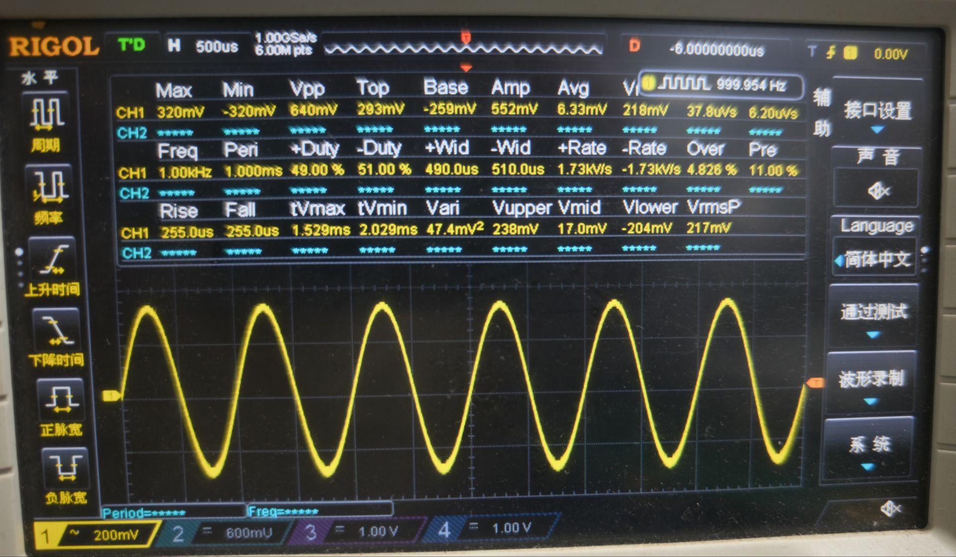
图4中测试频率:1KHz ,输出正弦波 。
图5
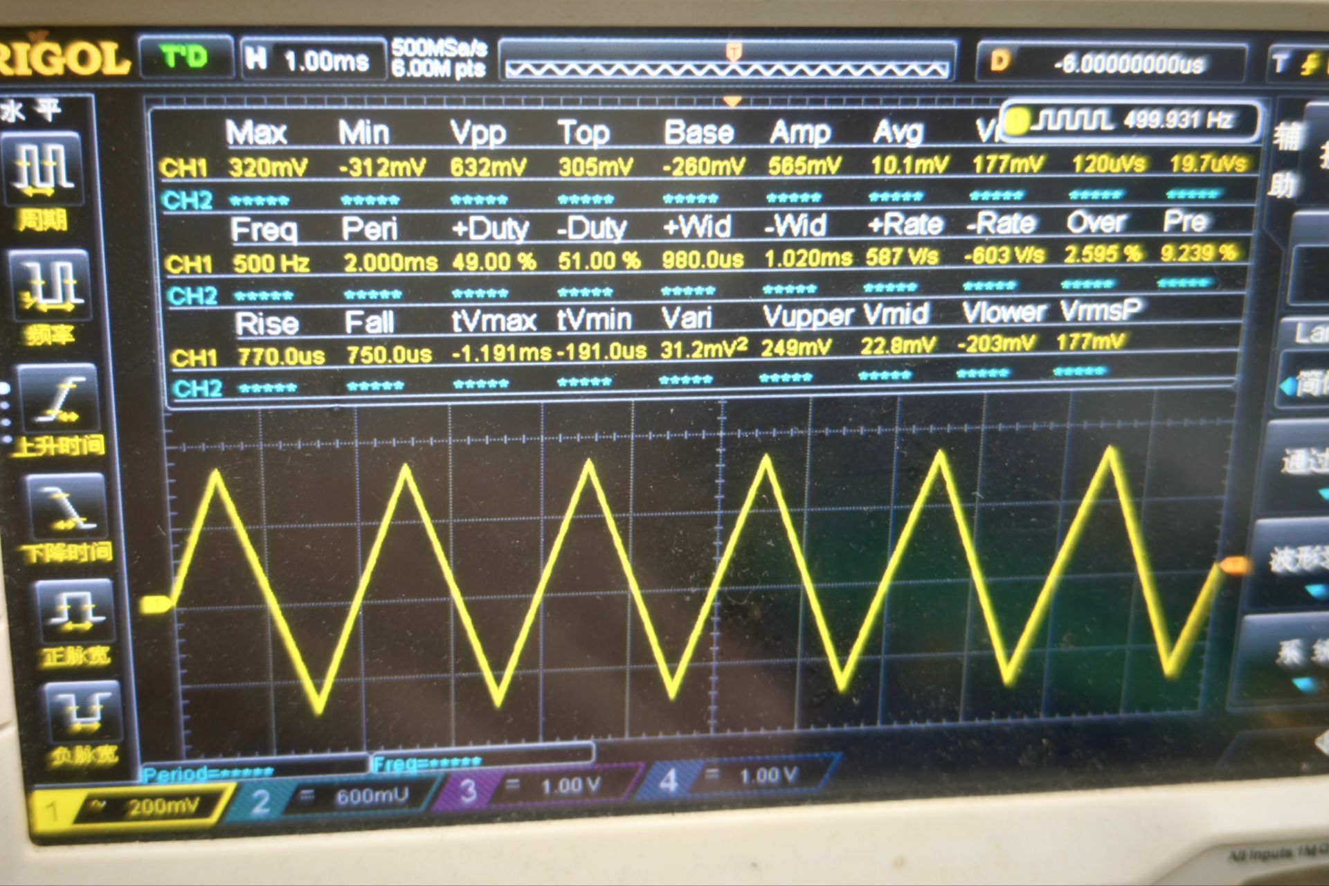
图5中测试频率:500Hz ,输出三角波 。
图6
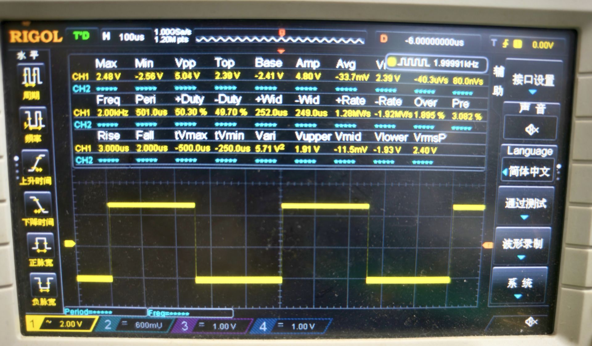
图6中测试率:2KHz ,输出方波 。
图7
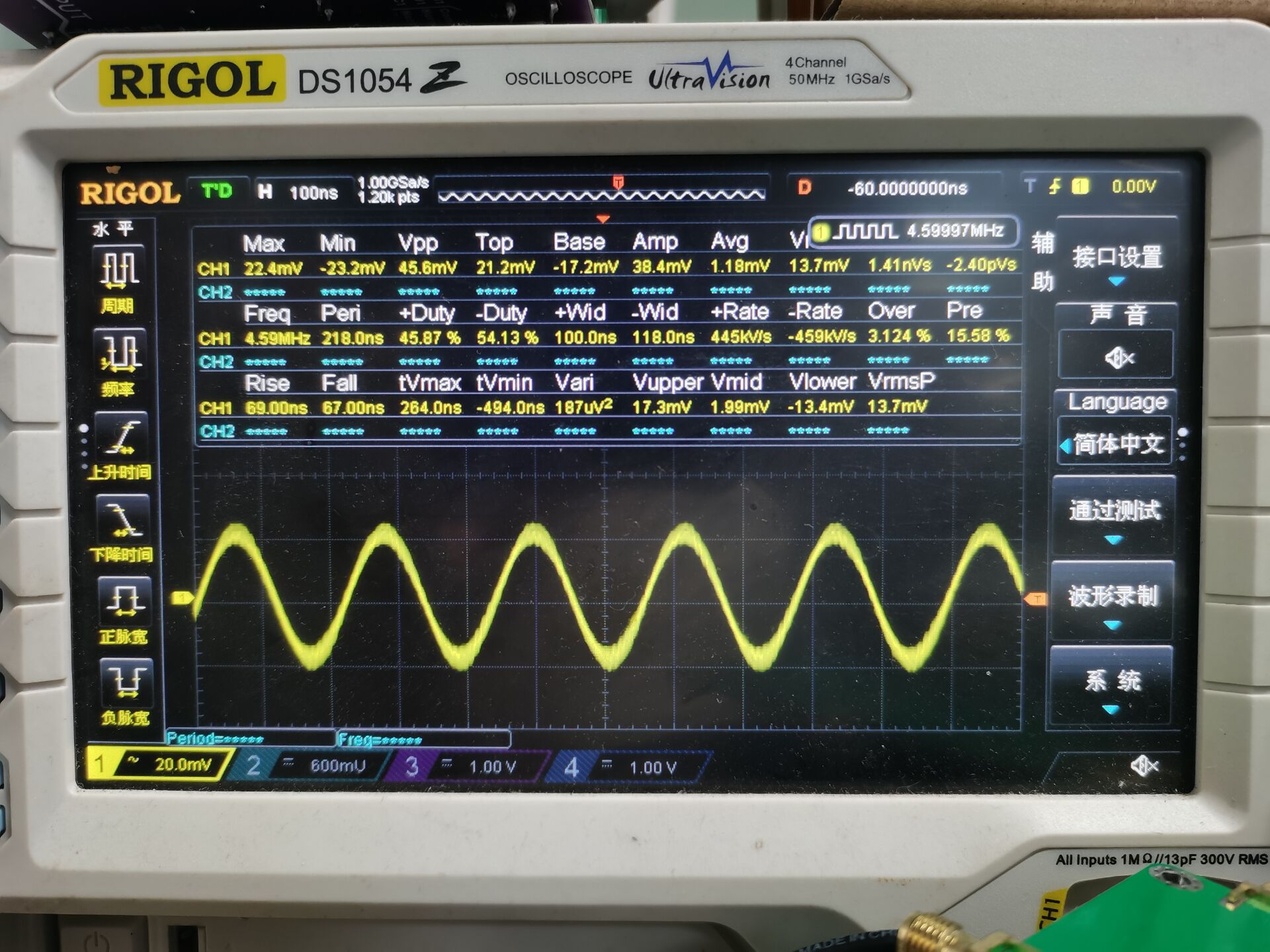
图7中波形是本次测试硬件最大频率稳定波形图,带宽频率:4.59MHz.,输出正弦波。
下面是超出硬件带宽5MHz,测试数据图形:
图8
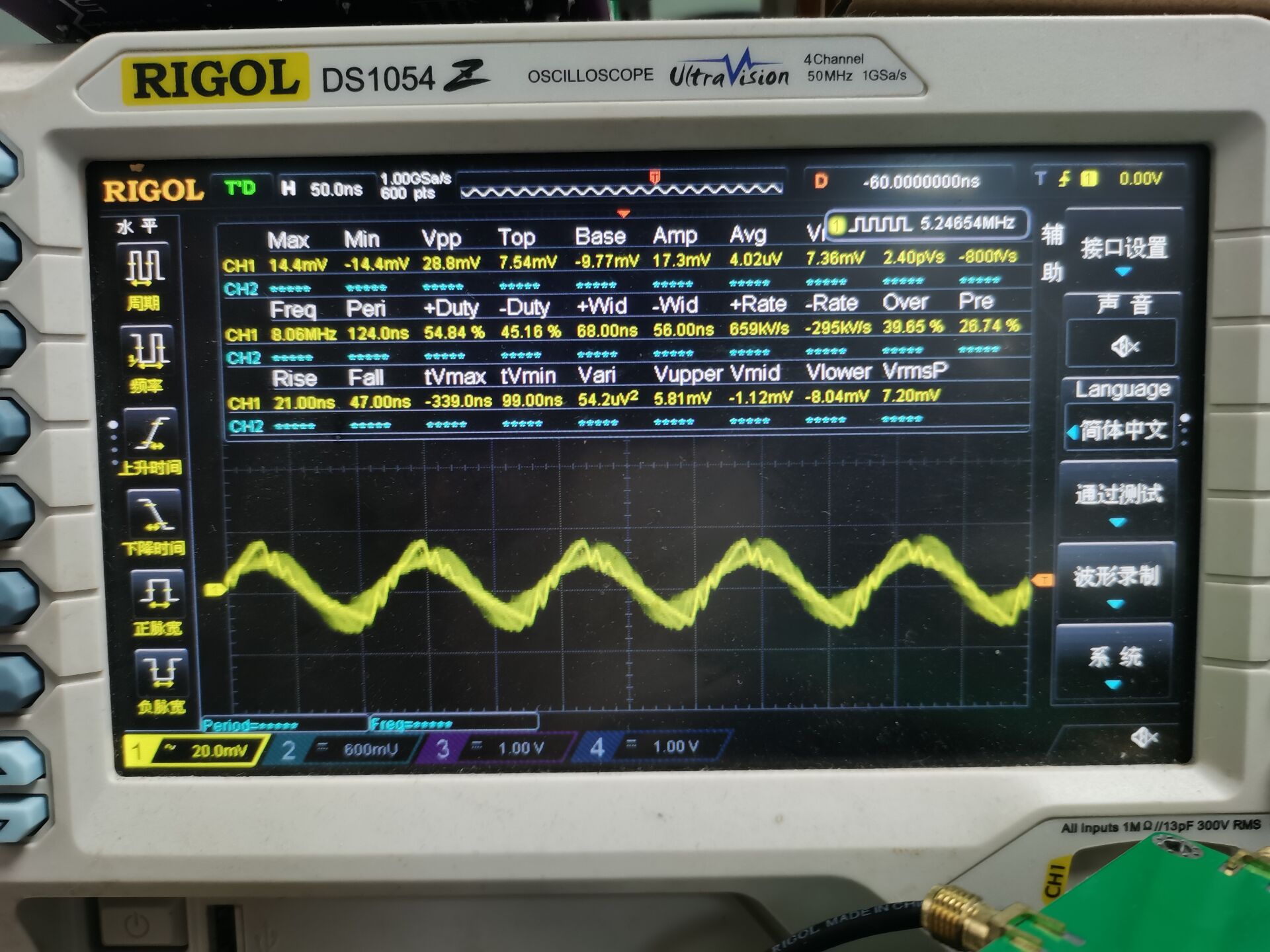
图9
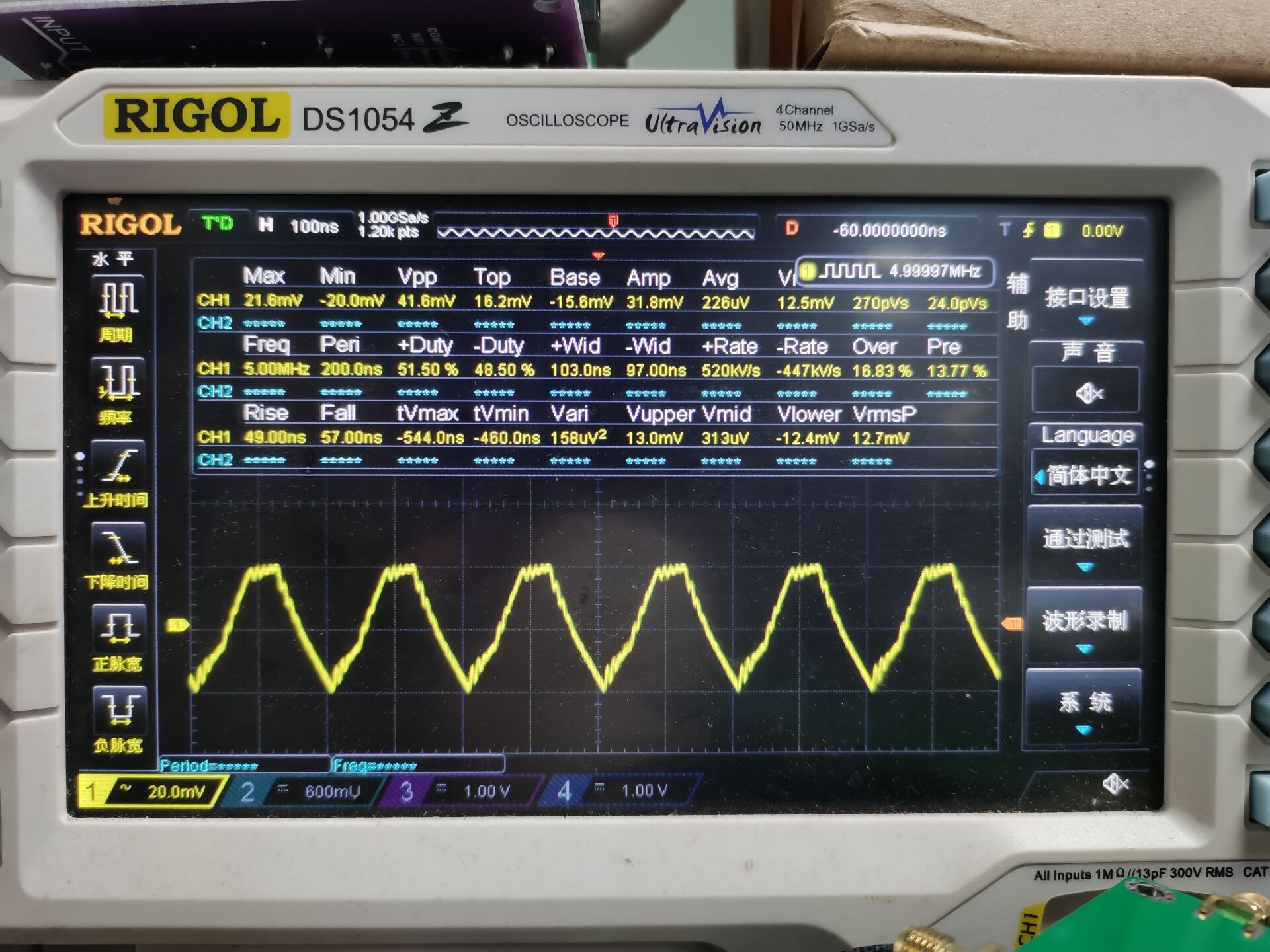
图10
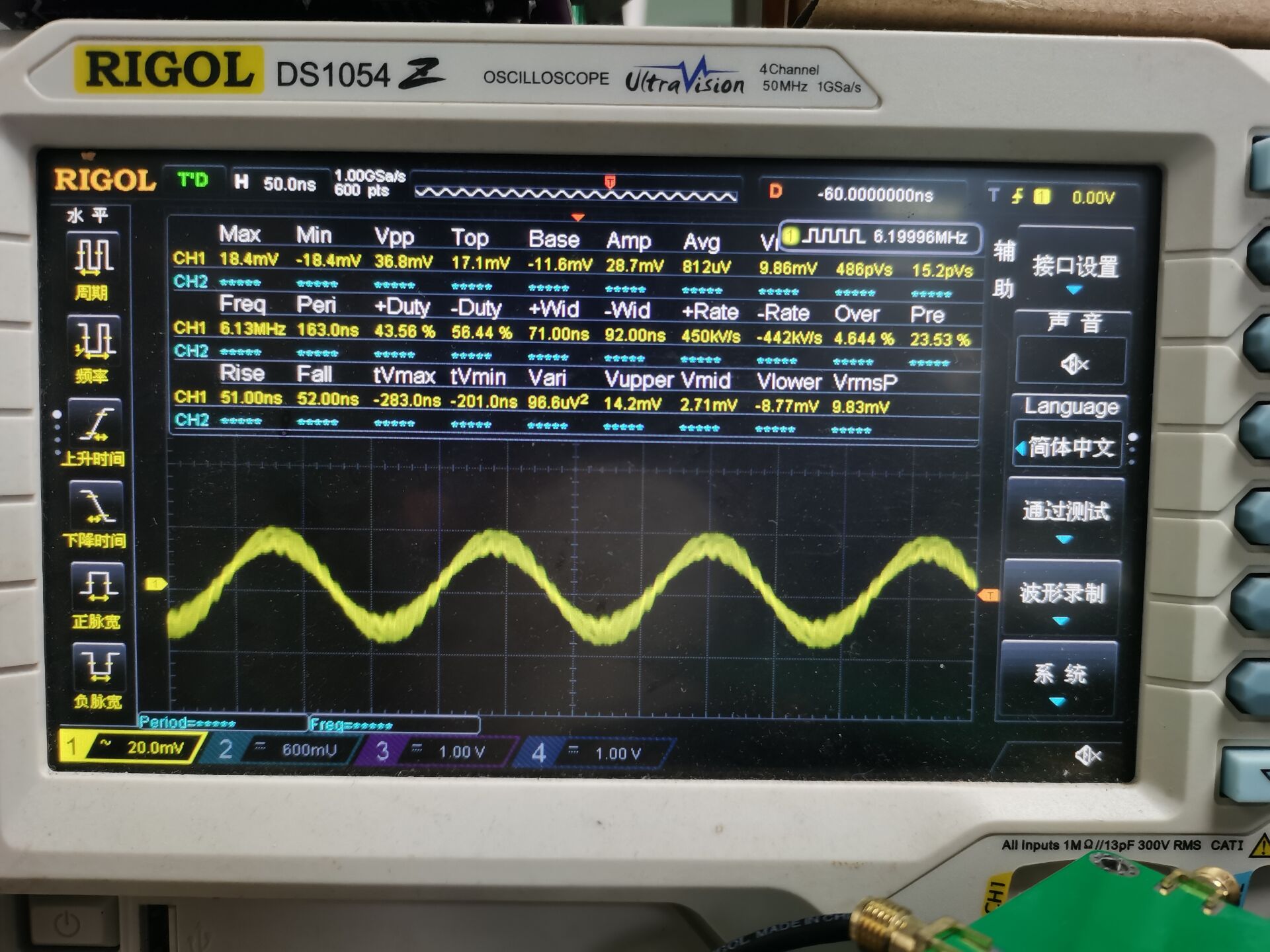
从图8,图9,图10波形图中可以看出测试的波形已经突变了!
总结
AD9833 是一款将数字世界的精确性与模拟世界连接起来的桥梁芯片。 它让用户能够以极低的成本和简单的操作,生成一个在传统模拟电路中需要复杂、昂贵且不稳定的元器件才能产生的精密波形。对于任何需要可编程信号源的项目来说,它都是一个非常出色的选择。
所以本文通过结合硬件和软件简单测试 ,展示AD9833基本功能使用步骤。
感谢你能看到这里!CGC

智能硬件社区聚焦AI智能硬件技术生态,汇聚嵌入式AI、物联网硬件开发者,打造交流分享平台,同步全国赛事资讯、开展 OPC 核心人才招募,助力技术落地与开发者成长。
更多推荐


 17
17 0
0- 0


 已为社区贡献3条内容

所有评论(0)