ESP32S3 Korvo2V3使用afe实现四通道aec配置
在小智方案下实现
ESP-IDF v5.4.1
esp-sr v2.1.5
实现四通道(双mic+ref+空)的aec回声消除
Korvo2V3硬件信息
在硬件层面上,该板使用ES7210作为输入音频控制,总共有4个mic位。
当前korvo板安装了两个mic分别连接mic1 和mic2位置 mic3连接ES8311的输出通道,将音频输出作为回采发送给7210的mic3用于回声消除。
我们的目标是全部打开四个通道,按照“MRMN”的数据格式喂给AEC算法,从而得到回声消除后的数据。
数据序列对各个配置对照:
|
数据形式 |
M |
R |
M |
N |
|
mic(7210) |
mic1 |
mic3 |
mic2 |
mic4 |
|
slot(I2S) |
0 |
2 |
1 |
3 |
|
channel(7210) |
1 |
3 |
2 |
4 |
|
channel_mask |
0 |
1 |
2 |
3 |
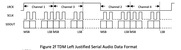
上图为es7210在当前配置下的输出格式
Codec配置
korvo2V3板使用的是ES8311+ES7210的组合配置,使用box_audio_codec 以下为codec配置
boxaudiocodec的构造函数:
BoxAudioCodec::BoxAudioCodec(void* i2c_master_handle, int input_sample_rate, int output_sample_rate,
    gpio_num_t mclk, gpio_num_t bclk, gpio_num_t ws, gpio_num_t dout, gpio_num_t din,
    gpio_num_t pa_pin, uint8_t es8311_addr, uint8_t es7210_addr, bool input_reference) {
    duplex_ = true; // 是否双工
    input_reference_ = input_reference; // 是否使用参考输入,实现回声消除
    input_channels_ = 4; // 输入通道数
    input_sample_rate_ = input_sample_rate;
    output_sample_rate_ = output_sample_rate;

    CreateDuplexChannels(mclk, bclk, ws, dout, din);

    // Do initialize of related interface: data_if, ctrl_if and gpio_if
    audio_codec_i2s_cfg_t i2s_cfg = {
        .port = I2S_NUM_0,
        .rx_handle = rx_handle_,
        .tx_handle = tx_handle_,
    };
    data_if_ = audio_codec_new_i2s_data(&i2s_cfg);
    assert(data_if_ != NULL);

    // Output
    audio_codec_i2c_cfg_t i2c_cfg = {
        .port = (i2c_port_t)1,
        .addr = es8311_addr,
        .bus_handle = i2c_master_handle,
    };
    out_ctrl_if_ = audio_codec_new_i2c_ctrl(&i2c_cfg);
    assert(out_ctrl_if_ != NULL);

    gpio_if_ = audio_codec_new_gpio();
    assert(gpio_if_ != NULL);

    es8311_codec_cfg_t es8311_cfg = {};
    es8311_cfg.ctrl_if = out_ctrl_if_;
    es8311_cfg.gpio_if = gpio_if_;
    es8311_cfg.codec_mode = ESP_CODEC_DEV_WORK_MODE_DAC;
    es8311_cfg.pa_pin = pa_pin;
    es8311_cfg.use_mclk = true;
    es8311_cfg.hw_gain.pa_voltage = 5.0;
    es8311_cfg.hw_gain.codec_dac_voltage = 3.3;
    out_codec_if_ = es8311_codec_new(&es8311_cfg);
    assert(out_codec_if_ != NULL);

    esp_codec_dev_cfg_t dev_cfg = {
        .dev_type = ESP_CODEC_DEV_TYPE_OUT,
        .codec_if = out_codec_if_,
        .data_if = data_if_,
    };
    output_dev_ = esp_codec_dev_new(&dev_cfg);
    assert(output_dev_ != NULL);

    // Input
    i2c_cfg.addr = es7210_addr;
    in_ctrl_if_ = audio_codec_new_i2c_ctrl(&i2c_cfg);
    assert(in_ctrl_if_ != NULL);

    es7210_codec_cfg_t es7210_cfg = {};
    es7210_cfg.ctrl_if = in_ctrl_if_;
    es7210_cfg.mic_selected = ES7120_SEL_MIC1 | ES7120_SEL_MIC2 | ES7120_SEL_MIC3 | ES7120_SEL_MIC4;
    in_codec_if_ = es7210_codec_new(&es7210_cfg);
    assert(in_codec_if_ != NULL);

    dev_cfg.dev_type = ESP_CODEC_DEV_TYPE_IN;
    dev_cfg.codec_if = in_codec_if_;
    input_dev_ = esp_codec_dev_new(&dev_cfg);
    assert(input_dev_ != NULL);

    ESP_LOGI(TAG, "BoxAudioDevice initialized");
}
input_channels
input_channels的数量代表输入的通道数,在现在的版本中,这个值可以用以下接口获取
inline int input_channels() const { return input_channels_; }而这个值在业务中只会影响这里:
size_t AfeAudioProcessor::GetFeedSize() {
    if (afe_data_ == nullptr) {
        return 0;
    }
    return afe_iface_->get_feed_chunksize(afe_data_) * codec_->input_channels();
}
在给afe喂数据之前需要知道数据大小,这里通过乘以通道数可以获得准确feedsize
es7210_cfg.mic_selected
这个配置是es7210用于开启mic通道的配置项,由于我们要开启四通道,所以选择全开:
es7210_cfg.mic_selected = ES7120_SEL_MIC1 | ES7120_SEL_MIC2 | ES7120_SEL_MIC3 | ES7120_SEL_MIC4; //这里ES7120是官方错误,就这么写RX TDM I2S配置
输入通道,在tdm模式下的I2S配置
.slot_cfg = {
            .data_bit_width = I2S_DATA_BIT_WIDTH_16BIT,
            .slot_bit_width = I2S_SLOT_BIT_WIDTH_AUTO,
            .slot_mode = I2S_SLOT_MODE_STEREO,
            .slot_mask = i2s_tdm_slot_mask_t(I2S_TDM_SLOT0 | I2S_TDM_SLOT1 | I2S_TDM_SLOT2 | I2S_TDM_SLOT3),
            .ws_width = I2S_TDM_AUTO_WS_WIDTH,
            .ws_pol = false,
            .bit_shift = true,
            .left_align = false,
            .big_endian = false,
            .bit_order_lsb = false,
            .skip_mask = false,
            .total_slot = I2S_TDM_AUTO_SLOT_NUM
        }
关键点在于要4个slot_mask全开 如果上一项的mic全开代表7210写入i2s时写入四通道,这里的slot全开就代表通过i2s读取数据时读取四通道
sample读取配置
这里作为读取i2s数据的最前线,决定最终读取的数据格式和一些调整。
void BoxAudioCodec::EnableInput(bool enable) {
    if (enable == input_enabled_) {
        return;
    }
    if (enable) {
        esp_codec_dev_sample_info_t fs = {
            .bits_per_sample = 16,
            .channel = 4,
            .channel_mask = 0,
            .sample_rate = (uint32_t)output_sample_rate_,
            .mclk_multiple = 0,
        };
        ESP_ERROR_CHECK(esp_codec_dev_open(input_dev_, &fs));
        ESP_ERROR_CHECK(esp_codec_dev_set_in_channel_gain(input_dev_, ESP_CODEC_DEV_MAKE_CHANNEL_MASK(0), 60.0));
        ESP_ERROR_CHECK(esp_codec_dev_set_in_channel_gain(input_dev_, ESP_CODEC_DEV_MAKE_CHANNEL_MASK(1), 60.0));
    } else {
        ESP_ERROR_CHECK(esp_codec_dev_close(input_dev_));
    }
    AudioCodec::EnableInput(enable);
}
这样配置就是代表:读取四个通道、每个通道一次读取16bit数据、并且为0,1通道配置增益(mic1和mic2)
注意:
channel_mask是通道过滤的意思,设为0代表所有通道都读取,此时读取到的数据序列就是[mic1, ref, mic2 null.......]四个通道数据交错排列
当设置某几个mask后,读取到的数据就只有这几个channel的数据
例如:
channel_mask = ESP_CODEC_DEV_MAKE_CHANNEL_MASK(0) | ESP_CODEC_DEV_MAKE_CHANNEL_MASK(1)这样配置两个过滤后,数据序列为 [mic1, ref ,mic1,ref.......]
Afe_audio_processor配置
首先确定input_format的值,这个配置决定输入给afe算法的数据格式,按照MRMN的格式排列
std::string input_format; input_format = "MRMN";
afe_config_t* afe_config = afe_config_init(input_format.c_str(), models, AFE_TYPE_SR, AFE_MODE_HIGH_PERF);
这里要选择AFE_TYPE_SR模式,因为这个模式支持四通道输入,常用的VC模式只支持mic+ref的双通道输入
输出
配置成功将在monitor中看到以下信息
ES7210:
I (1638) ES7210: Enable ES7210_INPUT_MIC1
I (1638) ES7210: Enable ES7210_INPUT_MIC2
I (1638) ES7210: Enable ES7210_INPUT_MIC3
I (1648) ES7210: Enable ES7210_INPUT_MIC4
I (1648) ES7210: Enable TDM mode
I2S:
I (1658) I2S_IF: channel mode 2 bits:16/16 channel:4 mask:f
I (1668) I2S_IF: TDM Mode 0 bits:16/16 channel:4 sample_rate:16000 mask:f
AFE:
I (7688) AFE: Input PCM Config: total 4 channels(2 microphone, 1 playback), sample rate:16000
I (7688) AFE: AFE Pipeline: [input] -> |AEC(VOIP_HIGH_PERF)| -> |SE(BSS)| -> [output]
智能硬件社区聚焦AI智能硬件技术生态,汇聚嵌入式AI、物联网硬件开发者,打造交流分享平台,同步全国赛事资讯、开展 OPC 核心人才招募,助力技术落地与开发者成长。
更多推荐

 25
25 0
0- 0


 已为社区贡献1条内容

所有评论(0)