stm32F103C8T6标准库系统非阻塞程序结构与扫描按键2
·
1.代码
1.1 主函数
1.1.1 main.h
#ifndef _MAIN_H
#define _MAIN_H

#include "led/app_led.h"
#include "idr/app_idr.h"
#include "key/app_key.h"

#endif  /*_MAIN_H*/
1.1.2 main.c
/**
  ******************************************************************************
  * @file    main.c
  * @author  作者
  * @version v1.0
  * @date    2026.4.28
  * @brief   非阻塞程序结构与扫描按键标准库写法
  ******************************************************************************
  * @attention
  *
  * 版权声明
  *
  ******************************************************************************
  */
#include "main.h"
#include "led/bsp_gpio_led.h"
#include "systick/bsp_systick.h"
#include "idr/bsp_gpio_idr.h"
#include "key/bsp_gpio_key.h"
#include "stm32f10x.h"


/*
   ************************程序设计要求*****************************************
   *                                                                           *
   *         1.编译并下载程序到开发板即可观察现象;                            *
   *         2.观察板载绿灯以500ms翻转状态。                                   *
   *         3.改变光敏传感器周围的光照,来切换LED灯状态。                     *
   *         4.短按KEY1核心板蓝灯亮,长按KEY1红灯亮,释放按键灭灯              *
   *         注意:每一个功能不可阻塞过多影响其他功能                          *
   *
   *                                                                           *
   *****************************************************************************

*/

/**
  * @brief  主函数
  * @param  无
  * @note   无
  * @retval 无
  */

int main (void)
{
    NVIC_PriorityGroupConfig(NVIC_PriorityGroup_4);
    LED_GPIO_Config();
    IDR_GPIO_Config();
    KEY_Init(&key1_info);

    ProgramRunLed_TaskInit(500);
    Idr_TaskInit(100);
    Key_TaskInit(20);
    SysTick_Init();

    while(1)
    {
        /*程序运行指示灯*/
//        LED_TOGGLE(G_LED2_GPIO_PORT, G_LED2_GPIO_PIN);
//        SysTick_DelayMS(time_temp);

//        /*光照强*/
//        if (IDR_Scan(IDR_GPIO_PORT, IDR_GPIO_PIN) == Bit_RESET)
//        {
//            LED_GPIO_OFF(LED4_GPIO_PORT, LED4_GPIO_PIN, LED_LOW_TRIGGER);
//        }
//        else/*光照弱*/
//        {
//            LED_GPIO_ON(LED4_GPIO_PORT, LED4_GPIO_PIN, LED_LOW_TRIGGER);
//        }
        //1. 不要空等
        //2.没有达到条件(时间、外部状态、更慢的数据),越过、跳过、短执行

        /* 程序正常指示灯 */
        ProgramRunLed_Task();

        /* 外界光照环境感应灯 */
        Idr_Task();

        /* 按键长短触发灯 */
        Key_Task();
    }
}
1.2 定时器
1.2.1 stm32f10x_it.c
/**
  ******************************************************************************
  * @file    GPIO/IOToggle/stm32f10x_it.c
  * @author  MCD Application Team
  * @version V3.6.0
  * @date    20-September-2021
  * @brief   Main Interrupt Service Routines.
  *          This file provides template for all exceptions handler and peripherals
  *          interrupt service routine.
  ******************************************************************************
  * @attention
  *
  * Copyright (c) 2011 STMicroelectronics.
  * All rights reserved.
  *
  * This software is licensed under terms that can be found in the LICENSE file
  * in the root directory of this software component.
  * If no LICENSE file comes with this software, it is provided AS-IS.
  *
  ******************************************************************************
  */

/* Includes ------------------------------------------------------------------*/
#include "stm32f10x_it.h"
#include "systick/bsp_systick.h"
#include "main.h"

/** @addtogroup STM32F10x_StdPeriph_Examples
  * @{
  */

/** @addtogroup GPIO_IOToggle
  * @{
  */

/* Private typedef -----------------------------------------------------------*/
/* Private define ------------------------------------------------------------*/
/* Private macro -------------------------------------------------------------*/
/* Private variables ---------------------------------------------------------*/
/* Private function prototypes -----------------------------------------------*/
/* Private functions ---------------------------------------------------------*/

/******************************************************************************/
/*            Cortex-M3 Processor Exceptions Handlers                         */
/******************************************************************************/

/**
  * @brief  This function handles NMI exception.
  * @param  None
  * @retval None
  */
void NMI_Handler(void)
{
}

/**
  * @brief  This function handles Hard Fault exception.
  * @param  None
  * @retval None
  */
void HardFault_Handler(void)
{
  /* Go to infinite loop when Hard Fault exception occurs */
  while (1)
  {
  }
}

/**
  * @brief  This function handles Memory Manage exception.
  * @param  None
  * @retval None
  */
void MemManage_Handler(void)
{
  /* Go to infinite loop when Memory Manage exception occurs */
  while (1)
  {
  }
}

/**
  * @brief  This function handles Bus Fault exception.
  * @param  None
  * @retval None
  */
void BusFault_Handler(void)
{
  /* Go to infinite loop when Bus Fault exception occurs */
  while (1)
  {
  }
}

/**
  * @brief  This function handles Usage Fault exception.
  * @param  None
  * @retval None
  */
void UsageFault_Handler(void)
{
  /* Go to infinite loop when Usage Fault exception occurs */
  while (1)
  {
  }
}

/**
  * @brief  This function handles SVCall exception.
  * @param  None
  * @retval None
  */
void SVC_Handler(void)
{
}

/**
  * @brief  This function handles Debug Monitor exception.
  * @param  None
  * @retval None
  */
void DebugMon_Handler(void)
{
}

/**
  * @brief  This function handles PendSV_Handler exception.
  * @param  None
  * @retval None
  */
void PendSV_Handler(void)
{
}

/**
  * @brief  This function handles SysTick Handler.
  * @param  None
  * @retval None
  */
void SysTick_Handler(void)
{
    SysTick_CountPlus();
    if (program_run_led_task.timer > 0x00)
    {
        program_run_led_task.timer--;
        if (program_run_led_task.timer == 0)
        {
            program_run_led_task.flag = 1;
        }
    }

    if (idr_led_task.timer > 0x00)
    {
        idr_led_task.timer--;
        if (idr_led_task.timer == 0)
        {
            idr_led_task.flag = 1;
        }
    }
    if (key_task.timer > 0x00)
    {
        key_task.timer--;
        if (key_task.timer == 0)
        {
            key_task.flag = 1;
        }
    }
}

/******************************************************************************/
/*                 STM32F10x Peripherals Interrupt Handlers                   */
/*  Add here the Interrupt Handler for the used peripheral(s) (PPP), for the  */
/*  available peripheral interrupt handler's name please refer to the startup */
/*  file (startup_stm32f10x_xx.s).                                            */
/******************************************************************************/

/**
  * @brief  This function handles PPP interrupt request.
  * @param  None
  * @retval None
  */
/*void PPP_IRQHandler(void)
{
}*/

/**
  * @}
  */

/**
  * @}
  */
1.2.2 bsp_systick.h
#ifndef __BSP_SYSTICK_H
#define __BSP_SYSTICK_H

#include "stm32f10x.h"

void SysTick_Init(void);
void SysTick_CountPlus(void);
uint64_t SysTick_GetCount(void);
void SysTick_DelayMS(uint64_t time);
#endif /*__BSP_SYSTICK_H*/
1.2.3 bsp_systick.c
/**
  ******************************************************************************
  * @file    bsp_gpio_systick.c
  * @author  作者
  * @version v1.0
  * @date    2026.4.23
  * @brief   系统定时器函数接口
  ******************************************************************************
  * @attention
  *
  * 版权声明
  *
  ******************************************************************************
  */
#include "systick/bsp_systick.h"


static uint64_t systick_count = 0;
 /**
  * @brief  初始化 SysTick (默认使用ms中断)
  * @param  无
  * @note   无
  * @retval 无
  */
void SysTick_Init(void)
{
    /*
    SystemCoreClock / 1000              1ms中断一次
    SystemCoreClock / 100000            10us中断一次
    SystemCoreClock / 1000000           1us中断一次
    */

    if (SysTick_Config(SystemCoreClock / 1000))   //1ms中断一次
    {
        while(1); //初始化失败后一直死循环在这,也可方便debug排查
    }

//    SysTick->CTRL &= ~SysTick_CTRL_ENABLE_Msk;   //关闭定时器
}

 /**
  * @brief  sysTick 循环计数函数
  * @param  无
  * @note   在 SysTick 中断函数 SysTick_Handler()内调用
  * @retval 无
  */
void SysTick_CountPlus(void)
{
    systick_count++;
}

 /**
  * @brief  查询当前 sysTick 循环计数的计数值
  * @param  无
  * @note   无
  * @retval 当前 sysTick 循环计数的计数值
  */
uint64_t SysTick_GetCount(void)
{
    return systick_count;
}

 /**
  * @brief  systick 查询寄存器延时函数接口
  * @param  time:传入计数值
  * @note   使用时开启Systick和配置对应计时频率 延时完毕后关闭, SysTick_Config()里默认开启了中断,但暂未在 SysTick 中断函数 SysTick_Handler()的函数体内写内容
  * @retval 无
  */
void SysTick_DelayMS(uint64_t time)
{
    uint64_t tick_start = SysTick_GetCount();
    while(SysTick_GetCount() - tick_start < time);
}
/***************************************END OF FILE *********************************************************/
1.3 LED灯
1.3.1 bsp_gpio_led.h
#ifndef __bsp_gpio_led_H
#define __bsp_gpio_led_H

#include "stm32f10x.h"

/*定义连接GPIO端口,用户只需要修改下面代码即可改变控制的LED引脚 */


//LED1
#define LED1_GPIO_PORT      GPIOA                       /* GPIO 端口 */
#define LED1_GPIO_CLK_PORT  RCC_APB2Periph_GPIOA        /* GPIO 端口时钟 */
#define LED1_GPIO_PIN       GPIO_Pin_1                  /* 对应PIN脚 */

//LED2
#define LED2_GPIO_PORT      GPIOA                       /* GPIO 端口 */
#define LED2_GPIO_CLK_PORT  RCC_APB2Periph_GPIOA        /* GPIO 端口时钟 */
#define LED2_GPIO_PIN       GPIO_Pin_2                 /* 对应PIN脚 */

//LED3
#define LED3_GPIO_PORT      GPIOA                       /* GPIO 端口 */
#define LED3_GPIO_CLK_PORT  RCC_APB2Periph_GPIOA        /* GPIO 端口时钟 */
#define LED3_GPIO_PIN       GPIO_Pin_3                  /* 对应PIN脚 */

//LED4
#define LED4_GPIO_PORT      GPIOB                       /* GPIO 端口 */
#define LED4_GPIO_CLK_PORT  RCC_APB2Periph_GPIOB        /* GPIO 端口时钟 */
#define LED4_GPIO_PIN       GPIO_Pin_5                  /* 对应PIN脚 */

/***************核心板载LED灯****************************************/

//R_LED
#define R_LED1_GPIO_PORT      LED1_GPIO_PORT            /* GPIO 端口 */
#define R_LED1_GPIO_CLK_PORT  LED1_GPIO_CLK_PORT        /* GPIO 端口时钟 */
#define R_LED1_GPIO_PIN       LED1_GPIO_PIN             /* 对应PIN脚 */

//G_LED
#define G_LED2_GPIO_PORT      LED2_GPIO_PORT            /* GPIO 端口 */
#define G_LED2_GPIO_CLK_PORT  LED2_GPIO_CLK_PORT        /* GPIO 端口时钟 */
#define G_LED2_GPIO_PIN       LED2_GPIO_PIN             /* 对应PIN脚 */

//B_LED
#define B_LED3_GPIO_PORT      LED3_GPIO_PORT            /* GPIO 端口 */
#define B_LED3_GPIO_CLK_PORT  LED3_GPIO_CLK_PORT        /* GPIO 端口时钟 */
#define B_LED3_GPIO_PIN       LED3_GPIO_PIN             /* 对应PIN脚 */


/***************用户自定义宏****************************************/
//R_LED
#define R_LED_ON_ONLY  LED_GPIO_ON(R_LED1_GPIO_PORT, R_LED1_GPIO_PIN, LED_LOW_TRIGGER);  \
                      LED_GPIO_OFF(G_LED2_GPIO_PORT, G_LED2_GPIO_PIN, LED_LOW_TRIGGER); \
                      LED_GPIO_OFF(B_LED3_GPIO_PORT, B_LED3_GPIO_PIN, LED_LOW_TRIGGER);

//G_LED
#define G_LED_ON_ONLY LED_GPIO_OFF(R_LED1_GPIO_PORT, R_LED1_GPIO_PIN, LED_LOW_TRIGGER);  \
                       LED_GPIO_ON(G_LED2_GPIO_PORT, G_LED2_GPIO_PIN, LED_LOW_TRIGGER); \
                      LED_GPIO_OFF(B_LED3_GPIO_PORT, B_LED3_GPIO_PIN, LED_LOW_TRIGGER);

//B_LED
#define B_LED_ON_ONLY LED_GPIO_OFF(R_LED1_GPIO_PORT, R_LED1_GPIO_PIN, LED_LOW_TRIGGER);  \
                      LED_GPIO_OFF(G_LED2_GPIO_PORT, G_LED2_GPIO_PIN, LED_LOW_TRIGGER); \
                       LED_GPIO_ON(B_LED3_GPIO_PORT, B_LED3_GPIO_PIN, LED_LOW_TRIGGER);

//B_G_B_LED全亮
#define RGB_LED_ALL_ON    LED_GPIO_ON(R_LED1_GPIO_PORT, R_LED1_GPIO_PIN, LED_LOW_TRIGGER);  \
                          LED_GPIO_ON(G_LED2_GPIO_PORT, G_LED2_GPIO_PIN, LED_LOW_TRIGGER); \
                          LED_GPIO_ON(B_LED3_GPIO_PORT, B_LED3_GPIO_PIN, LED_LOW_TRIGGER);

//B_G_B_LED全灭
#define RGB_LED_ALL_OFF     LED_GPIO_OFF(R_LED1_GPIO_PORT, R_LED1_GPIO_PIN, LED_LOW_TRIGGER);  \
                            LED_GPIO_OFF(G_LED2_GPIO_PORT, G_LED2_GPIO_PIN, LED_LOW_TRIGGER); \
                            LED_GPIO_OFF(B_LED3_GPIO_PORT, B_LED3_GPIO_PIN, LED_LOW_TRIGGER);

/* LED 灯亮时的IO电平 */
typedef enum {
    LED_LOW_TRIGGER = 0,
    LED_HIGH_TRIGGER = 1,
}LED_TriggerLever;

void LED_GPIO_Config(void);
void LED_GPIO_ON(GPIO_TypeDef* GPIOx, uint16_t GPIO_Pin, LED_TriggerLever led_brightstatus);
void LED_GPIO_OFF(GPIO_TypeDef* GPIOx, uint16_t GPIO_Pin, LED_TriggerLever led_brightstatus);
void LED_TOGGLE(GPIO_TypeDef* GPIOx, uint16_t GPIO_Pin);

#endif /*__bsp_gpio_led_H*/
1.3.2 bsp_gpio_led.c
/**
  ******************************************************************************
  * @file    bsp_gpio_led.c
  * @author  作者
  * @version v1.0
  * @date    2026.4.3
  * @brief   LED灯的函数接口
  ******************************************************************************
  * @attention
  *
  * 版权声明
  *
  ******************************************************************************
  */
#include "led/bsp_gpio_led.h"

/**
  * @brief  初始化控制 LED 的IO
  * @param  无
  * @retval 无
  */

void LED_GPIO_Config(void)
{
    GPIO_InitTypeDef GPIO_InitStruct = { 0 };
/*****************************核心板载LED****************************************/
#if 1

    RCC_APB2PeriphClockCmd(R_LED1_GPIO_CLK_PORT, ENABLE); //开启GPIOA 端口时钟

    GPIO_SetBits(R_LED1_GPIO_PORT, R_LED1_GPIO_PIN);    //设置PA1端口初始化1 让LED灭

    // 配置引脚:选择GPIOA的Pin1
    GPIO_InitStruct.GPIO_Pin = R_LED1_GPIO_PIN;
    // 配置输出速度:50MHz
    GPIO_InitStruct.GPIO_Speed = GPIO_Speed_50MHz;
    // 配置工作模式:推挽输出
    GPIO_InitStruct.GPIO_Mode = GPIO_Mode_Out_PP;
    GPIO_Init(R_LED1_GPIO_PORT, &GPIO_InitStruct);
#endif

#if 1

    RCC_APB2PeriphClockCmd(G_LED2_GPIO_CLK_PORT, ENABLE); //开启GPIOA 端口时钟

    GPIO_SetBits(G_LED2_GPIO_PORT, G_LED2_GPIO_PIN);    //设置PA2端口初始化1 让LED灭

    // 配置引脚:选择GPIOA的Pin1
    GPIO_InitStruct.GPIO_Pin = G_LED2_GPIO_PIN;
    // 配置输出速度:50MHz
    GPIO_InitStruct.GPIO_Speed = GPIO_Speed_50MHz;
    // 配置工作模式:推挽输出
    GPIO_InitStruct.GPIO_Mode = GPIO_Mode_Out_PP;
    GPIO_Init(G_LED2_GPIO_PORT, &GPIO_InitStruct);
#endif

#if 1

    RCC_APB2PeriphClockCmd(B_LED3_GPIO_CLK_PORT, ENABLE); //开启GPIOA 端口时钟

    GPIO_SetBits(B_LED3_GPIO_PORT, B_LED3_GPIO_PIN);    //设置PA3端口初始化1 让LED灭

    // 配置引脚:选择GPIOA的Pin1
    GPIO_InitStruct.GPIO_Pin = B_LED3_GPIO_PIN;
    // 配置输出速度:50MHz
    GPIO_InitStruct.GPIO_Speed = GPIO_Speed_50MHz;
    // 配置工作模式:推挽输出
    GPIO_InitStruct.GPIO_Mode = GPIO_Mode_Out_PP;
    GPIO_Init(B_LED3_GPIO_PORT, &GPIO_InitStruct);
#endif

/*****************************用户自定义LED*******************************/
#if 1

    RCC_APB2PeriphClockCmd(LED4_GPIO_CLK_PORT, ENABLE);

    GPIO_SetBits(LED4_GPIO_PORT, LED4_GPIO_PIN);

    // 配置引脚:选择GPIOA的Pin1
    GPIO_InitStruct.GPIO_Pin = LED4_GPIO_PIN;
    // 配置输出速度:50MHz
    GPIO_InitStruct.GPIO_Speed = GPIO_Speed_50MHz;
    // 配置工作模式:推挽输出
    GPIO_InitStruct.GPIO_Mode = GPIO_Mode_Out_PP;
    GPIO_Init(LED4_GPIO_PORT, &GPIO_InitStruct);
#endif

}

/**
  * @brief  开启对应 LED 灯
  * @param  GPIOX : x可以是 A,B,C等
  * @param  GPIO_PIN: 待操作的PIN
  * @param  led_brightstatus LED灯亮时的状态
  * @retval 无
  */
void LED_GPIO_ON(GPIO_TypeDef* GPIOx, uint16_t GPIO_Pin, LED_TriggerLever led_brightstatus)
{
    if (led_brightstatus == LED_LOW_TRIGGER)
    {
        GPIO_ResetBits(GPIOx, GPIO_Pin);
    }
    else
    {
        GPIO_SetBits(GPIOx, GPIO_Pin);
    }
}

/**
  * @brief  关闭对应 LED 灯
  * @param  GPIOX : x可以是 A,B,C等
  * @param  GPIO_PIN: 待操作的PIN
  * @param  led_brightstatus LED灯亮时的状态
  * @retval 无
  */
void LED_GPIO_OFF(GPIO_TypeDef* GPIOx, uint16_t GPIO_Pin, LED_TriggerLever led_brightstatus)
{
    if (led_brightstatus == LED_LOW_TRIGGER)
    {
        GPIO_SetBits(GPIOx, GPIO_Pin);
    }
    else
    {
        GPIO_ResetBits(GPIOx, GPIO_Pin);
    }
}

/**
  * @brief  翻转对应 LED 灯
  * @param  GPIOX : x可以是 A,B,C等
  * @param  GPIO_PIN: 待操作的PIN
  * @retval 无
  */
 void LED_TOGGLE(GPIO_TypeDef* GPIOx, uint16_t GPIO_Pin)
{
    GPIOx->ODR ^= GPIO_Pin;
}
/***************************************END OF FILE *********************************************************/
1.3.3 app_led.h
#ifndef __APP_LED_H
#define __APP_LED_H

#include "stm32f10x.h"

/*定义连接GPIO端口,用户只需要修改下面代码即可改变控制的LED引脚 */
typedef struct
{
    uint32_t cycle;     //周期
    int32_t timer;      //时间
    uint8_t flag;       //标志
}Led_TaskInfo; /*LED任务信息*/

extern Led_TaskInfo program_run_led_task;

void ProgramRunLed_TaskReset(void);
void ProgramRunLed_TaskInit(uint32_t program_run_led_task_cycle);
void ProgramRunLed_Task(void);

#endif /*__APP_LED_H*/
1.3.4 app_led.c
/**
  ******************************************************************************
  * @file    App_led.c
  * @author  作者
  * @version v1.0
  * @date    2026.4.3
  * @brief   LED灯应用层功能接口
  ******************************************************************************
  * @attention
  *
  * 版权声明
  *
  ******************************************************************************
  */
#include "led/app_led.h"
#include "led/bsp_gpio_led.h"

/*初始化 程序运行LED任务 变量*/
Led_TaskInfo program_run_led_task = { 0 };

/**
  * @brief  程序正常运行指示灯 计数复位
  * @param  无
  * @retval 无
  */
void ProgramRunLed_TaskReset(void)
{
    program_run_led_task.timer = program_run_led_task.cycle;
    program_run_led_task.flag = 0;
}

/**
  * @brief  程序正常运行指示灯 任务初始化
  * @param  program_run_led_task_cycle: 任务周期 单位ms(可修改系统节拍定时器)
  * @retval 无
  */
void ProgramRunLed_TaskInit(uint32_t program_run_led_task_cycle)
{
    program_run_led_task.cycle = program_run_led_task_cycle;
    ProgramRunLed_TaskReset();
}

/**
  * @brief  程序正常运行指示灯 任务
  * @param  无
  * @retval 无
  */
void ProgramRunLed_Task(void)
{
    if (program_run_led_task.flag == 1)
    {
        LED_TOGGLE(G_LED2_GPIO_PORT, G_LED2_GPIO_PIN);
        ProgramRunLed_TaskReset();
    }
}
/***************************************END OF FILE *********************************************************/
1.4 光敏传感器
1.4.1 bsp_gpio_idr.h
#ifndef __BSP_GPIO_IDR_H
#define __BSP_GPIO_IDR_H

#include "stm32f10x.h"

/*定义连接GPIO端口,用户只需要修改下面代码即可改变控制的LED引脚 */

//idr_D0
#define IDR_GPIO_PORT      GPIOA                       /* GPIO 端口 */
#define IDR_GPIO_CLK_PORT  RCC_APB2Periph_GPIOA        /* GPIO 端口时钟 */
#define IDR_GPIO_PIN       GPIO_Pin_11                 /* 对应PIN脚 */


void IDR_GPIO_Config(void);
BitAction IDR_Scan(GPIO_TypeDef* GPIOx, uint16_t GPIO_Pin);

#endif /*__BSP_GPIO_IDR_H*/
1.4.2 bsp_gpio_idr.c
/**
  ******************************************************************************
  * @file    bsp_gpio_idr.c
  * @author  作者
  * @version v1.0
  * @date    2026.4.3
  * @brief   光敏传感器的函数接口
  ******************************************************************************
  * @attention
  *
  * 版权声明
  *
  ******************************************************************************
  */
#include "idr/bsp_gpio_idr.h"

/**
  * @brief  初始化控制 光敏传感器 的IO
  * @param  无
  * @retval 无
  */

void IDR_GPIO_Config(void)
{
    GPIO_InitTypeDef GPIO_InitStruct = { 0 };

/*****************************核心板载按键****************************************/

#if 1
    /*开启GPIOA 端口时钟*/
    RCC_APB2PeriphClockCmd(IDR_GPIO_CLK_PORT, ENABLE);

    /*设置PA11端口初始化高电平*/
    GPIO_SetBits(IDR_GPIO_PORT, IDR_GPIO_PIN);

    // 配置引脚:选择GPIOA的Pin1
    GPIO_InitStruct.GPIO_Pin = IDR_GPIO_PIN;
    // 配置输出速度:50MHz
    GPIO_InitStruct.GPIO_Speed = GPIO_Speed_50MHz;
    // 配置工作模式:浮空输入模式
    GPIO_InitStruct.GPIO_Mode = GPIO_Mode_IN_FLOATING;

    GPIO_Init(IDR_GPIO_PORT, &GPIO_InitStruct);
#endif

}
/**
  * @brief  光敏传感检测
  * @param  GPIOX : x可以是 A,B,C等
  * @param  GPIO_PIN: 待操作的PIN
  * @retval BitAction枚举类型 有两个成员Bit_SET = 1和Bit_RESET = 0
  * @retval Bit_SET(外界光照弱)、Bit_RESET(外界光照强)
  */
BitAction IDR_Scan(GPIO_TypeDef* GPIOx, uint16_t GPIO_Pin)
{
    if (GPIO_ReadInputDataBit(GPIOx, GPIO_Pin) == Bit_RESET)
    {
        return Bit_RESET;
    }
    else
    {
        return Bit_SET;
    }
}

/***************************************END OF FILE *********************************************************/
1.4.3 app_idr.h
#ifndef __APP_IDR_H
#define __APP_IDR_H

#include "stm32f10x.h"

/*定义连接GPIO端口,用户只需要修改下面代码即可改变控制的LED引脚 */
typedef struct
{
    uint32_t cycle;         //周期
    int32_t timer;          //时间
    uint8_t flag;           //标志
    char    device_id[10];  //设备ID
}Idr_TaskInfo; /*光敏任务信息*/

extern Idr_TaskInfo idr_led_task;

void Idr_TaskReset(void);
void Idr_TaskInit(uint32_t idr_led_task_cycle);
void Idr_Task(void);

#endif /*__APP_IDR_H*/
1.4.4 app_idr.c
/**
  ******************************************************************************
  * @file    App_idr.c
  * @author  作者
  * @version v1.0
  * @date    2026.4.3
  * @brief   光敏传感器应用层功能接口
  ******************************************************************************
  * @attention
  *
  * 版权声明
  *
  ******************************************************************************
  */
#include "idr/app_idr.h"
#include "idr/bsp_gpio_idr.h"
#include "led/bsp_gpio_led.h"

/*初始化 光敏传感器任务 变量*/
Idr_TaskInfo idr_led_task = { 0 };

/**
  * @brief  外界光照感应灯 计数复位
  * @param  无
  * @retval 无
  */
void Idr_TaskReset(void)
{
    idr_led_task.timer = idr_led_task.cycle;
    idr_led_task.flag = 0;
}

/**
  * @brief  外界光照感应灯 任务初始化
  * @param  program_run_led_task_cycle: 任务周期 单位ms(可修改系统节拍定时器)
  * @retval 无
  */
void Idr_TaskInit(uint32_t idr_led_task_cycle)
{
    idr_led_task.cycle = idr_led_task_cycle;
    Idr_TaskReset();
}

/**
  * @brief  外界光照感应灯 任务
  * @param  无
  * @retval 无
  */
void Idr_Task(void)
{
    if (idr_led_task.flag == 1)
    {
        /*光照强*/
        if (IDR_Scan(IDR_GPIO_PORT, IDR_GPIO_PIN) == Bit_RESET)
        {
            LED_GPIO_OFF(LED4_GPIO_PORT, LED4_GPIO_PIN, LED_LOW_TRIGGER);
        }
        else/*光照弱*/
        {
            LED_GPIO_ON(LED4_GPIO_PORT, LED4_GPIO_PIN, LED_LOW_TRIGGER);
        }

        Idr_TaskReset();
    }
}
/***************************************END OF FILE *********************************************************/
1.5 按键
1.4.1 bsp_gpio_key.h
#ifndef __BSP_GPIO_KEY_H
#define __BSP_GPIO_KEY_H

#include "stm32f10x.h"

/*定义连接GPIO端口,用户只需要修改下面代码即可改变控制的LED引脚 */

/**********************核心板载按键****************************************/
//KEY1
#define KEY1_GPIO_PORT      GPIOA                       /* GPIO 端口 */
#define KEY1_GPIO_CLK_PORT  RCC_APB2Periph_GPIOA        /* GPIO 端口时钟 */
#define KEY1_GPIO_PIN       GPIO_Pin_0                  /* 对应PIN脚 */

//KEY2
#define KEY2_GPIO_PORT      GPIOC                       /* GPIO 端口 */
#define KEY2_GPIO_CLK_PORT  RCC_APB2Periph_GPIOC        /* GPIO 端口时钟 */
#define KEY2_GPIO_PIN       GPIO_Pin_13                 /* 对应PIN脚 */


/**********************用户自定义按键****************************************/
//KEY3
#define KEY3_GPIO_PORT      GPIOB                       /* GPIO 端口 */
#define KEY3_GPIO_CLK_PORT  RCC_APB2Periph_GPIOB        /* GPIO 端口时钟 */
#define KEY3_GPIO_PIN       GPIO_Pin_15                 /* 对应PIN脚 */

//KEY4
#define KEY4_GPIO_PORT      GPIOB                       /* GPIO 端口 */
#define KEY4_GPIO_CLK_PORT  RCC_APB2Periph_GPIOB        /* GPIO 端口时钟 */
#define KEY4_GPIO_PIN       GPIO_Pin_6                 /* 对应PIN脚 */

//KEY5
#define KEY5_GPIO_PORT      GPIOB                       /* GPIO 端口 */
#define KEY5_GPIO_CLK_PORT  RCC_APB2Periph_GPIOB        /* GPIO 端口时钟 */
#define KEY5_GPIO_PIN       GPIO_Pin_7                 /* 对应PIN脚 */

//KEY6
#define KEY6_GPIO_PORT      GPIOB                       /* GPIO 端口 */
#define KEY6_GPIO_CLK_PORT  RCC_APB2Periph_GPIOB        /* GPIO 端口时钟 */
#define KEY6_GPIO_PIN       GPIO_Pin_8                 /* 对应PIN脚 */

/* 按键按下时的IO电平 */
typedef enum {
    KEY_LOW_TRIGGER = 0,
    KEY_HIGH_TRIGGER = 1,
    KEY_GENERAL_TRIGGER = 2,
}KEY_TriggerLevel;

/* 按键的状态 */
typedef enum {
    KEY_UP = 0,
    KEY_DOWN = 1,
    KEY_INIT = 2,
}KEY_Status;


/* 按键的事件类型 */
typedef enum {
    EVENT_ATTONITY      = 0,  /* 空闲状态 */
    EVENT_PRESS         = 1,  /* 按下状态 */
    EVENT_SHORT         = 2,  /* 短按状态 */
    EVENT_SHORT_RELEASE = 3,  /* 短按释放状态 */
    EVENT_LONG          = 4,  /* 长按状态 */
    EVENT_LONG_RELEASE  = 5,  /* 长按释放状态 */
}KEY_Evnet;

/* 按键的点击类型 */
typedef enum {
    KEY_NONE_CLICK       = 0,
    KEY_SINGLE_CLICK     = 1,   /*单击*/
    KEY_DOUBLE_CLICK     = 2,   /*双击*/
    KEY_LONG_CLICK       = 3,   /*按键长按*/
}KEY_ClickType;


/* 按键结构体 */
typedef struct
{
    GPIO_TypeDef*    GPIOx;
    uint16_t         GPIO_Pin;
    KEY_TriggerLevel triggerLevel;      /* 按下时电平状态 */
    KEY_Status       status;            /* 按键的状态 */
    uint64_t         press_time;        /* 按下时间 */
    uint64_t         release_time;      /* 释放时间 */
    KEY_Evnet        evnet;             /* 按键事件 */
    KEY_ClickType    clicktype;         /* 按键点击类型 */
}KEY_Info;


extern KEY_Info key1_info;

void KEY_GPIO_Config(void);
KEY_Status KEY_Scan(GPIO_TypeDef* GPIOx, uint16_t GPIO_Pin, KEY_TriggerLevel key_pressstatus);
void KeyLevel_Init(KEY_Info* key_info);
void KEY_Init(KEY_Info* key_info);
KEY_Evnet KEY_SystickScan(KEY_Info* key_info);
#endif /*__BSP_GPIO_KEY_H*/
1.4.2 bsp_gpio_key.c
/**
  ******************************************************************************
  * @file    bsp_gpio_key.c
  * @author  作者
  * @version v1.0
  * @date    2026.4.3
  * @brief   扫描按键函数接口
  ******************************************************************************
  * @attention
  *
  * 版权声明
  *
  ******************************************************************************
  */
#include "key/bsp_gpio_key.h"
#include "delay/bsp_delay.h"
#include "systick/bsp_systick.h"

KEY_Info key1_info = { KEY1_GPIO_PORT, KEY1_GPIO_PIN, KEY_GENERAL_TRIGGER, KEY_INIT, 0,0,EVENT_ATTONITY,KEY_NONE_CLICK};

/**
  * @brief  初始化控制 KEY 的IO
  * @param  无
  * @retval 无
  */

void KEY_GPIO_Config(void)
{
    GPIO_InitTypeDef GPIO_InitStruct = { 0 };

/*****************************核心板载按键****************************************/

#if 1

    RCC_APB2PeriphClockCmd(KEY1_GPIO_CLK_PORT, ENABLE); //开启GPIOA 端口时钟

    GPIO_SetBits(KEY1_GPIO_PORT, KEY1_GPIO_PIN);    //设置PA0端口初始化1 让LED灭

    // 配置引脚:选择GPIOA的Pin1
    GPIO_InitStruct.GPIO_Pin = KEY1_GPIO_PIN;
    // 配置输出速度:50MHz
    GPIO_InitStruct.GPIO_Speed = GPIO_Speed_50MHz;
    // 配置工作模式:浮空输入模式
    GPIO_InitStruct.GPIO_Mode = GPIO_Mode_IN_FLOATING;
    GPIO_Init(KEY1_GPIO_PORT, &GPIO_InitStruct);
#endif

#if 0

    RCC_APB2PeriphClockCmd(KEY2_GPIO_CLK_PORT, ENABLE); //开启GPIOA 端口时钟

    GPIO_SetBits(KEY2_GPIO_PORT, KEY2_GPIO_PIN);

    // 配置引脚:选择GPIOA的Pin1
    GPIO_InitStruct.GPIO_Pin = KEY2_GPIO_PIN;
    // 配置输出速度:50MHz
    GPIO_InitStruct.GPIO_Speed = GPIO_Speed_50MHz;
    // 配置工作模式:浮空输入模式
    GPIO_InitStruct.GPIO_Mode = GPIO_Mode_IN_FLOATING;
    GPIO_Init(KEY2_GPIO_PORT, &GPIO_InitStruct);
#endif

/*****************************用户自定义扩展按键****************************************/
#if 0

    RCC_APB2PeriphClockCmd(KEY3_GPIO_CLK_PORT, ENABLE);

    GPIO_SetBits(KEY3_GPIO_PORT, KEY3_GPIO_PIN);

    // 配置引脚:选择GPIOA的Pin1
    GPIO_InitStruct.GPIO_Pin = KEY3_GPIO_PIN;
    // 配置输出速度:50MHz
    GPIO_InitStruct.GPIO_Speed = GPIO_Speed_50MHz;
    // 配置工作模式:下拉输入模式
    GPIO_InitStruct.GPIO_Mode = GPIO_Mode_IPD;
    GPIO_Init(KEY3_GPIO_PORT, &GPIO_InitStruct);
#endif

#if 0

    RCC_APB2PeriphClockCmd(KEY4_GPIO_CLK_PORT, ENABLE);

    GPIO_SetBits(KEY4_GPIO_PORT, KEY4_GPIO_PIN);

    // 配置引脚:选择GPIOA的Pin1
    GPIO_InitStruct.GPIO_Pin = KEY4_GPIO_PIN;
    // 配置输出速度:50MHz
    GPIO_InitStruct.GPIO_Speed = GPIO_Speed_50MHz;
    // 配置工作模式:上拉输入模式
    GPIO_InitStruct.GPIO_Mode = GPIO_Mode_IPU;
    GPIO_Init(KEY4_GPIO_PORT, &GPIO_InitStruct);
#endif

#if 0

    RCC_APB2PeriphClockCmd(KEY5_GPIO_CLK_PORT, ENABLE);

    GPIO_SetBits(KEY5_GPIO_PORT, KEY5_GPIO_PIN);

    // 配置引脚:选择GPIOA的Pin1
    GPIO_InitStruct.GPIO_Pin = KEY5_GPIO_PIN;
    // 配置输出速度:50MHz
    GPIO_InitStruct.GPIO_Speed = GPIO_Speed_50MHz;
    // 配置工作模式:上拉输入模式
    GPIO_InitStruct.GPIO_Mode = GPIO_Mode_IPU;
    GPIO_Init(KEY5_GPIO_PORT, &GPIO_InitStruct);
#endif

#if 0

    RCC_APB2PeriphClockCmd(KEY6_GPIO_CLK_PORT, ENABLE);

    GPIO_SetBits(KEY6_GPIO_PORT, KEY6_GPIO_PIN);

    // 配置引脚:选择GPIOA的Pin1
    GPIO_InitStruct.GPIO_Pin = KEY6_GPIO_PIN;
    // 配置输出速度:50MHz
    GPIO_InitStruct.GPIO_Speed = GPIO_Speed_50MHz;
    // 配置工作模式:上拉输入模式
    GPIO_InitStruct.GPIO_Mode = GPIO_Mode_IPU;
    GPIO_Init(KEY6_GPIO_PORT, &GPIO_InitStruct);
#endif


}

/**
  * @brief  基础检测按键
  * @param  GPIOX : x可以是 A,B,C等
  * @param  GPIO_PIN: 待操作的PIN
  * @param  key_pressstatus:按键按下时IO电平状态
  * @retval KEY_UP(没有触发按键)、KEY_DOWN(触发按键)
  */
KEY_Status KEY_Scan(GPIO_TypeDef* GPIOx, uint16_t GPIO_Pin, KEY_TriggerLevel key_pressstatus)
{
    if (GPIO_ReadInputDataBit(GPIOx, GPIO_Pin) == key_pressstatus)
    {
        Rough_Delay_Ms(20);
        while(GPIO_ReadInputDataBit(GPIOx, GPIO_Pin) == key_pressstatus);
        Rough_Delay_Ms(20);
        return KEY_DOWN;
    }
    else
    {
        return KEY_UP;
    }
}

/**
  * @brief  获取当前操作按键电平
  * @param  key_info:   操作按键的信息结构体
  * @note   无
  * @retval 当前操作按键的电平
  */
static uint8_t Get_KeyCurrentLevel(KEY_Info* key_info)
{
    return GPIO_ReadInputDataBit(key_info->GPIOx, key_info->GPIO_Pin);
}

/**
  * @brief  获取当前操作按键空闲/抬起后的电平
  * @param  key_info:   操作按键的信息结构体
  * @note   无
  * @retval 无
  */
void KeyLevel_Init(KEY_Info* key_info)
{
    if (key_info->triggerLevel == KEY_GENERAL_TRIGGER)
    {
        /* 上电后程序启动短时间内默认按键未按,那么根据当前未按下电平,反推出按下的电平*/
        /* 设置按键按下后电平状态是高电平 */
        key_info->triggerLevel = Get_KeyCurrentLevel(key_info)? KEY_LOW_TRIGGER : KEY_HIGH_TRIGGER;


    }
}

/**
  * @brief  按键初始化
  * @param  无
  * @retval 无
  */
void KEY_Init(KEY_Info* key_info)
{
    /* 对应的 GPIO 配置 */
    KEY_GPIO_Config();

    /*按键电平初始化*/
    KeyLevel_Init(key_info);
}

/**
  * @brief  使用定时器扫描方式获取当前操作按键的事件类型
  * @param  key_info: 操作按键信息的结构体
  * @note   无
  * @retval 按键事件类型
  */
KEY_Evnet KEY_SystickScan(KEY_Info* key_info)
{
    uint64_t time_time = 0;
    /* 读取按键GPIO电平状态 与 按下后GPIO电平状态一致*/
    if (Get_KeyCurrentLevel(key_info) == key_info->triggerLevel)
    {
        key_info->status = KEY_DOWN;
    }
    else
    {
        key_info->status = KEY_UP;
    }

    switch(key_info->evnet)
    {
        case EVENT_ATTONITY:  /* 上一个事件处于 空闲/无操作 时 */
            if (key_info->status == KEY_DOWN)
            {
                key_info->evnet = EVENT_PRESS;
                key_info->press_time = SysTick_GetCount();
            }
            break;

        case EVENT_PRESS:  /* 上一个事件处于 按键按下 时 */
            if (key_info->status == KEY_DOWN)
            {
                time_time = SysTick_GetCount();
                /*按下时间超过自定义长按时间 还继续按下时 属于长按*/
                if (time_time - key_info->press_time > 1000)
                {
                    key_info->evnet = EVENT_LONG; /* 进入长按事件 */
                }

            }
            else
            {
                key_info->evnet = EVENT_SHORT;  /* 进入短按事件 */
            }
            break;

         case EVENT_SHORT:
            /*上一轮返回EVENT_SHORT,无进阶事件,重回EVENT_ATTONITY*/
            key_info->evnet = EVENT_SHORT_RELEASE;

            /*按键单击*/
            //key_info->clicktype = KEY_SINGLE_CLICK;
            break;

         case EVENT_LONG:
            if (key_info->status == KEY_DOWN)
            {
                 key_info->evnet = EVENT_LONG; /* 保持长按事件 */
            }
            else
            {
                /*上一轮返回EVENT_LONG,无进阶事件,重回EVENT_ATTONITY*/
                key_info->evnet = EVENT_LONG_RELEASE;

                /*按键长击*/
//                key_info->clicktype = KEY_LONG_CLICK;
            }
            break;

         default:
            key_info->evnet = EVENT_ATTONITY;
    }
    return key_info->evnet;
}
/***************************************END OF FILE *********************************************************/
1.4.3 app_key.h
#ifndef __APP_KEY_H
#define __APP_KEY_H

#include "stm32f10x.h"

/*定义连接GPIO端口,用户只需要修改下面代码即可改变控制的LED引脚 */
typedef struct
{
    uint32_t cycle;     //周期
    int32_t timer;      //时间
    uint8_t flag;       //标志
}Key_TaskInfo;          /*按键任务信息*/

extern Key_TaskInfo key_task;

void Key_TaskReset(void);
void Key_TaskInit(uint32_t key_task_cycle);
void Key_Task(void);

#endif /*__APP_LED_H*/
1.4.4 app_key.c
/**
  ******************************************************************************
  * @file    App_key.c
  * @author  作者
  * @version v1.0
  * @date    2026.4.3
  * @brief   按键应用层功能接口
  ******************************************************************************
  * @attention
  *
  * 版权声明
  *
  ******************************************************************************
  */

#include "key/app_key.h"
#include "led/bsp_gpio_led.h"
#include "key/bsp_gpio_key.h"

/*初始化 按键任务 变量*/
Key_TaskInfo key_task = { 0 };

/**
  * @brief  按键 计数复位
  * @param  无
  * @retval 无
  */
void Key_TaskReset(void)
{
    key_task.timer = key_task.cycle;
    key_task.flag = 0;
}

/**
  * @brief  按键 任务初始化
  * @param  key_task_cycle: 任务周期 单位ms(可修改系统节拍定时器)
  * @retval 无
  */
void Key_TaskInit(uint32_t key_task_cycle)
{
    key_task.cycle = key_task_cycle;
    Key_TaskReset();
}

/**
  * @brief  按键 任务
  * @param  无
  * @retval 无
  */
void Key_Task(void)
{
    if (key_task.flag == 1)
    {
        KEY_Evnet current_event;
        current_event = KEY_SystickScan(&key1_info);

        /* 短按蓝灯亮*/
        if (current_event == EVENT_SHORT)
        {
            LED_GPIO_ON(B_LED3_GPIO_PORT, B_LED3_GPIO_PIN, LED_LOW_TRIGGER);
        }
        /* 短按释放 蓝灯灭*/
        else if (current_event == EVENT_SHORT_RELEASE)
        {
            LED_GPIO_OFF(B_LED3_GPIO_PORT, B_LED3_GPIO_PIN, LED_LOW_TRIGGER);
        }

        /* 长按红灯亮 */
        if (current_event == EVENT_LONG)
        {
            LED_GPIO_ON(R_LED1_GPIO_PORT, R_LED1_GPIO_PIN, LED_LOW_TRIGGER);
        }
        /* 长按释放 红灯灭*/
        else if (current_event == EVENT_LONG_RELEASE)
        {
            LED_GPIO_OFF(R_LED1_GPIO_PORT, R_LED1_GPIO_PIN, LED_LOW_TRIGGER);
        }

//        /*单击事件*/
//        if (key1_info.clicktype == KEY_SINGLE_CLICK)
//        {
//            LED_TOGGLE(R_LED1_GPIO_PORT, R_LED1_GPIO_PIN);
//            key1_info.clicktype = KEY_NONE_CLICK;
//        }
        Key_TaskReset();
    }
}
/***************************************END OF FILE *********************************************************/
1.5 粗略延时
1.4.1 bsp_delay.h
#ifndef __bsp_delay_H
#define __bsp_delay_H

#include "stm32f10x.h"

void Rough_Delay(__IO uint32_t ncount);
void Rough_Delay_Us(__IO uint32_t ncount);
void Rough_Delay_Ms(__IO uint32_t time);
void Rough_Delay_S(__IO uint32_t time);

#endif /*__bsp_delay_H*/
1.4.2 bsp_delay.c
/**
  ******************************************************************************
  * @file    bsp_delay.c
  * @author  作者
  * @version v1.0
  * @date    2026.4.19
  * @brief   粗略阻塞延时函数接口
  ******************************************************************************
  * @attention
  *
  * 版权声明
  *
  ******************************************************************************
  */
#include "delay/bsp_delay.h"

/**
  * @brief  粗略阻塞延时基本函数接口
  * @param  ncount:传入的计数值
  * @note   软件延时函数,使用不同的系统时钟,延时不一样,还会存在函数调用以及其他计算损耗,只能粗略使用
  * @retval 无
  */

void Rough_Delay(__IO uint32_t ncount)
{
    for (uint32_t i = 0; i < ncount; i++)
    {
        __nop();
    }
}

/**
  * @brief  粗略阻塞延时基本函数接口    单位:US
  * @param  ncount:传入的计数值
  * @note   软件延时函数,使用不同的系统时钟,延时不一样,还会存在函数调用以及其他计算损耗,只能粗略使用
  * @retval 无
  */
void Rough_Delay_Us(__IO uint32_t time)
{
    Rough_Delay(time);
}

/**
  * @brief  粗略阻塞延时基本函数接口    单位:MS
  * @param  ncount:传入的计数值
  * @note   软件延时函数,使用不同的系统时钟,延时不一样,还会存在函数调用以及其他计算损耗,只能粗略使用
  * @retval 无
  */
void Rough_Delay_Ms(__IO uint32_t time)
{
    Rough_Delay(time * 1000);
}

/**
  * @brief  粗略阻塞延时基本函数接口    单位:S
  * @param  ncount:传入的计数值
  * @note   软件延时函数,使用不同的系统时钟,延时不一样,还会存在函数调用以及其他计算损耗,只能粗略使用
  * @retval 无
  */
void Rough_Delay_S(__IO uint32_t time)
{
    Rough_Delay(time * 1000 * 1000);
}
2.连线图
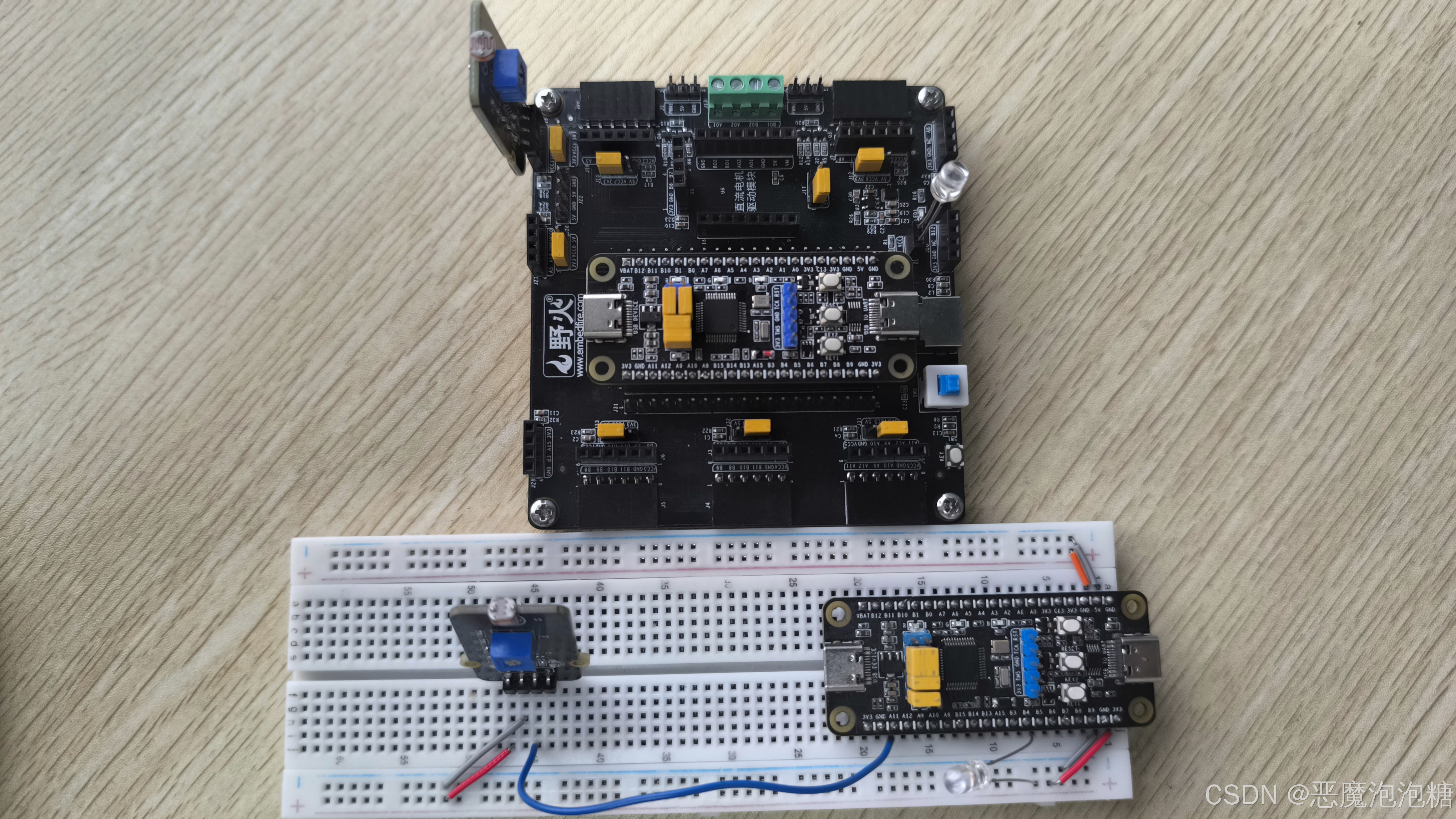
3.实验现象
非阻塞模式按键扫描

智能硬件社区聚焦AI智能硬件技术生态,汇聚嵌入式AI、物联网硬件开发者,打造交流分享平台,同步全国赛事资讯、开展 OPC 核心人才招募,助力技术落地与开发者成长。
更多推荐


 9
9 0
0- 0


 已为社区贡献22条内容

所有评论(0)