基于STM32矩阵电子密码锁设计
·
基于STM32密码锁设计
(仿真+程序+原理图+PCB)
功能介绍
具体功能:
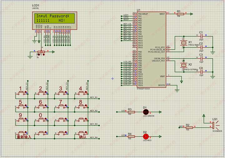
1.4x4矩阵键盘可输入6位密码并支持循环覆盖;
2.LCD1602实时显示输入的密码;
3.密码输入正确或错误有对应声光提示;
4.发现输入错误,可以重新输入;
添加图片注释,不超过 140 字(可选)
程序
#include <stdio.h>
#include <stdlib.h>
#include <string.h>
/***微信公众号:木子单片机****/
#include "main.h"
#include "lcd1602.h"
#include "timer.h"
#include "key4x4.h"
#include "beep.h"

void SystemClock_Config(void);

uint8_t flag = 0;

uint8_t password[6] = {1,  2,  3,  4,  5,  6};

uint8_t disp_num[6] = {27, 27, 27, 27, 27, 27};

uint8_t disp_num_tmp[6];

#define DISP_FORMAT "%d%d%d%d%d%d"

char *Disp_YES  = "    YES!  ";
char *Disp_NO   = "    NO!   ";
char *Disp_NONE = "          ";

char *toDisplay;

int main(void)
{
	uint8_t Key_Value = 27;
	uint8_t i = 0;

  /* Reset of all peripherals, Initializes the Flash interface and the Systick. */
  HAL_Init();
  /* Configure the system clock */
  SystemClock_Config();
  TIM3_Init(2400-1, 72-1); // 10ms

	Beep_Init();
	Key_Init();
	LCD_Init();

	LCD_write_string(0, 0, "Input Password:");

  while(1)
  {
		Key_Value = Key_Scan();

		if(Key_Value < 10)
		{
			disp_num[i] = Key_Value;
			i++;
			if(i > 5)
				i = 0;

			Key_Value = 27;
		}

		if(Key_Value == 16)
		{
			for(i = 0; i < 6; i++)
			{
				if(disp_num[i] != password[i])
				{
					flag = 1; //输入错误
					break;
				}
				else
				{
					flag = 0;
				}
			}

			if(flag == 1) //输入错误
			{
				LCD_write_string(6, 1, Disp_NO);
				LED_Blink (3, 200);
				BEEP_Blink(3, 200);
				LCD_write_string(6, 1, Disp_NONE);
			}
			else          //输入正确
			{
				LCD_write_string(6, 1, Disp_YES);
				LED_Blink (1, 500);
				BEEP_Blink(1, 500);
				LCD_write_string(6, 1, Disp_NONE);
			}

			memset(disp_num, 27, 6);
			Key_Value = 27;
			i = 0;
		}

		if(Key_Value == 13)
		{
			memset(disp_num, 27, 6);
			Key_Value = 27;
			i = 0;
		}

		for(uint8_t j = 0; j < 6; j++)
		{
			if(disp_num[j] > 9)
				disp_num_tmp[j] = 0;
			else
				disp_num_tmp[j] = disp_num[j];
		}
		sprintf(toDisplay, DISP_FORMAT, disp_num_tmp[0], disp_num_tmp[1], disp_num_tmp[2], disp_num_tmp[3], disp_num_tmp[4], disp_num_tmp[5]);

		HAL_Delay(20);
  }
}
******//完整资料
*****//***微信公众号:木子单片机****/
//定时器3中断服务函数
uint8_t led_temp = 0;
void TIM3_IRQHandler(void)
{
	 led_temp++;
	 if(led_temp > 10)
	 {
		 led_temp = 0;
		 LED1_TOG();

		 LCD_write_string(0, 1, toDisplay);
	 }

   HAL_TIM_IRQHandler(&TIM3_Handler);
}

/**
  * @brief System Clock Configuration
  * @retval None
**/
void SystemClock_Config(void)
{
  RCC_OscInitTypeDef RCC_OscInitStruct = {0};
  RCC_ClkInitTypeDef RCC_ClkInitStruct = {0};
  RCC_PeriphCLKInitTypeDef PeriphClkInit = {0};

  /** Initializes the CPU, AHB and APB busses clocks
  */
  RCC_OscInitStruct.OscillatorType = RCC_OSCILLATORTYPE_HSI|RCC_OSCILLATORTYPE_LSI;
  RCC_OscInitStruct.HSIState = RCC_HSI_ON;
  RCC_OscInitStruct.HSICalibrationValue = RCC_HSICALIBRATION_DEFAULT;
  RCC_OscInitStruct.LSIState = RCC_LSI_ON;
  RCC_OscInitStruct.PLL.PLLState = RCC_PLL_NONE;
  if (HAL_RCC_OscConfig(&RCC_OscInitStruct) != HAL_OK)
  {
  }
  /** Initializes the CPU, AHB and APB busses clocks
  */
  RCC_ClkInitStruct.ClockType = RCC_CLOCKTYPE_HCLK|RCC_CLOCKTYPE_SYSCLK
                              |RCC_CLOCKTYPE_PCLK1|RCC_CLOCKTYPE_PCLK2;
  RCC_ClkInitStruct.SYSCLKSource = RCC_SYSCLKSOURCE_HSI;
  RCC_ClkInitStruct.AHBCLKDivider = RCC_SYSCLK_DIV1;
  RCC_ClkInitStruct.APB1CLKDivider = RCC_HCLK_DIV2;
  RCC_ClkInitStruct.APB2CLKDivider = RCC_HCLK_DIV1;

  if (HAL_RCC_ClockConfig(&RCC_ClkInitStruct, FLASH_LATENCY_0) != HAL_OK)
  {
  }
  PeriphClkInit.PeriphClockSelection = RCC_PERIPHCLK_RTC|RCC_PERIPHCLK_ADC;
  PeriphClkInit.RTCClockSelection = RCC_RTCCLKSOURCE_LSI;
  PeriphClkInit.AdcClockSelection = RCC_ADCPCLK2_DIV2;
  if (HAL_RCCEx_PeriphCLKConfig(&PeriphClkInit) != HAL_OK)
  {
  }
}

/************************ (C) COPYRIGHT STMicroelectronics *****END OF FILE****/
硬件设计
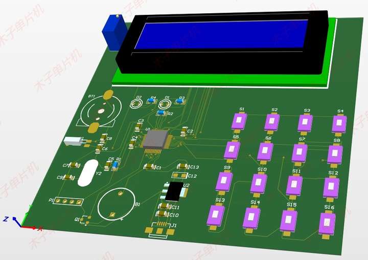
使用元器件:
单片机:STM32F103C;
添加图片注释,不超过 140 字(可选)
设计资料
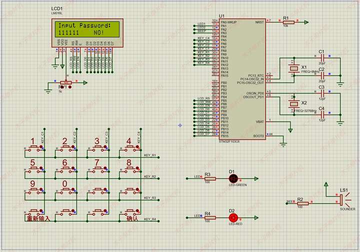
01仿真图
本设计使用proteus8.9版本设计!具体如图!
添加图片注释,不超过 140 字(可选)
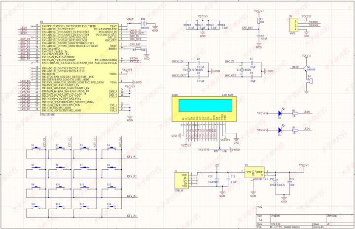
02原理图
本系统原理图采用Altium Designer19设计,具体如图!
添加图片注释,不超过 140 字(可选)
03程序
本设计使用Keil5 MDK版本编程设计!具体如图!
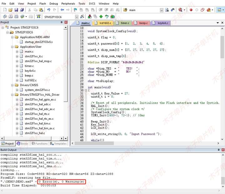
添加图片注释,不超过 140 字(可选)
04PCB
本系统PCB采用Altium Designer19设计,具体如图!
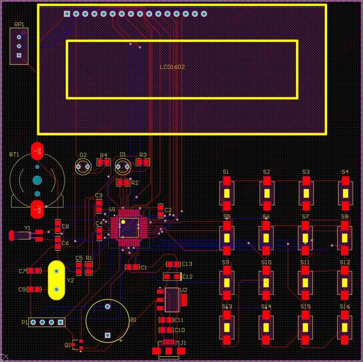
添加图片注释,不超过 140 字(可选)
05设计资料
全部资料包括仿真源文件 、程序(含注释)、AD原理图、PCB等。具体内容如下,全网最全! !

添加图片注释,不超过 140 字(可选)
点赞分享一起学习成长。

智能硬件社区聚焦AI智能硬件技术生态,汇聚嵌入式AI、物联网硬件开发者,打造交流分享平台,同步全国赛事资讯、开展 OPC 核心人才招募,助力技术落地与开发者成长。
更多推荐
 6
6 0
0- 0


 已为社区贡献9条内容

所有评论(0)