使用STM32实现无刷电机FOC矢量控制
前言
本文侧重工程实战,涵盖电机驱动算法、STM32CubeMX外设配置及硬件电路设计。作为一名硬件工程师,笔者将更多笔墨聚焦于落地实现,理论推导部分建议参考稚晖君的经典文章【自制FOC驱动器】深入浅出讲解FOC算法与SVPWM技术 - 知乎
关于浮点精度的选择,尽管STM32H750支持双精度运算,但本代码统一采用单精度浮点(float),主要基于两点考量:
1、跨平台兼容性:便于代码移植至F4、G4等仅支持单精度的主流MCU;
2、执行效率:在H750上,单精度运算的吞吐量依然优于双精度,更能满足FOC高频中断的实时性要求。
后续若有精力,笔者计划补充双精度优化及三角函数查表加速等进阶算法,欢迎关注更新。
CubeMX配置
定时器
简单介绍下为什么这样配置
-
Counter Mode: Center Aligned (中心对齐)
-
原因:生成对称 PWM,确保在计数顶点(5000附近)时下桥臂导通最稳定,为 ADC 提供无噪声的最佳采样窗口。
-
-
Counter Period (ARR): 5000
-
原因:设定开关频率。H750 定时器时钟 240MHz,中心对齐模式下频率为 $240M / (5000 \times 2) = \mathbf{24kHz}$,兼顾静音与低损耗。
-
-
Repetition Counter (RCR): 1
-
原因:抑制中断翻倍。中心对齐模式默认每个半周期触发一次中断,设 RCR=1 后,强制每个完整 PWM 周期只触发一次中断,匹配 FOC 控制频率。
-
-
TRGO Source: OC4REF (通道4比较输出)
-
原因:硬件硬同步。将定时器 CH4 事件直接作为 ADC 的启动信号,无需 CPU 干预,确保采样时刻精准可控。
-
-
Channel 4 Pulse (CCR4): 4900
-
原因:定位采样点。设为接近 ARR (5000) 的值(约98%),目的是让 ADC 在 PWM 波形的最高点附近启动转换,避开开关噪声。
-
-
Dead Time (死区时间)
-
原因:防炸机。在上下桥臂切换时插入微秒级延时,防止 MOSFET 直通短路。笔者配置为20,死区时间约为1.267μs,笔者配置的比较保守。
-
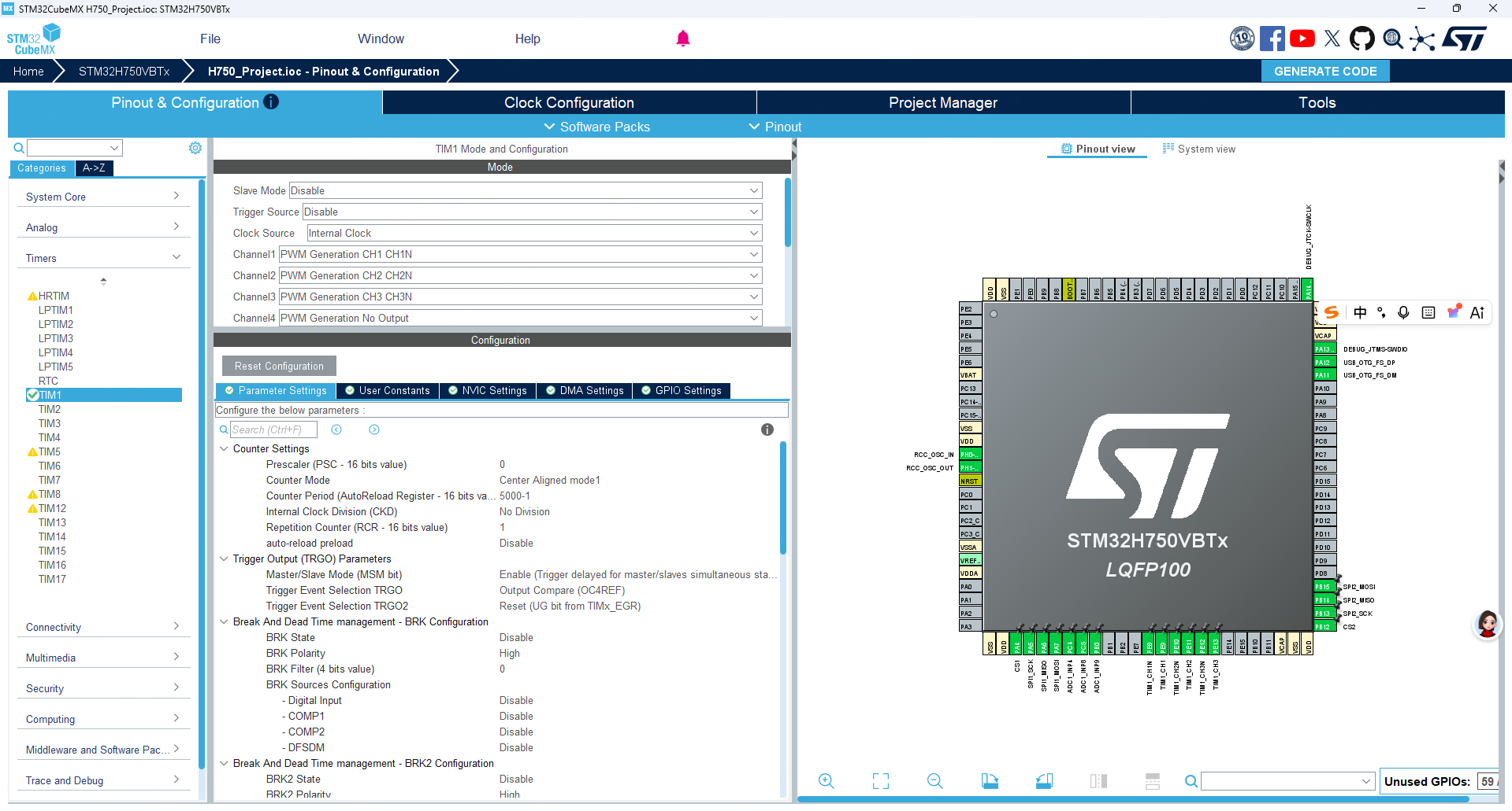
PWM CH1~3 配置是一样的所以就只展示了PWM CH1
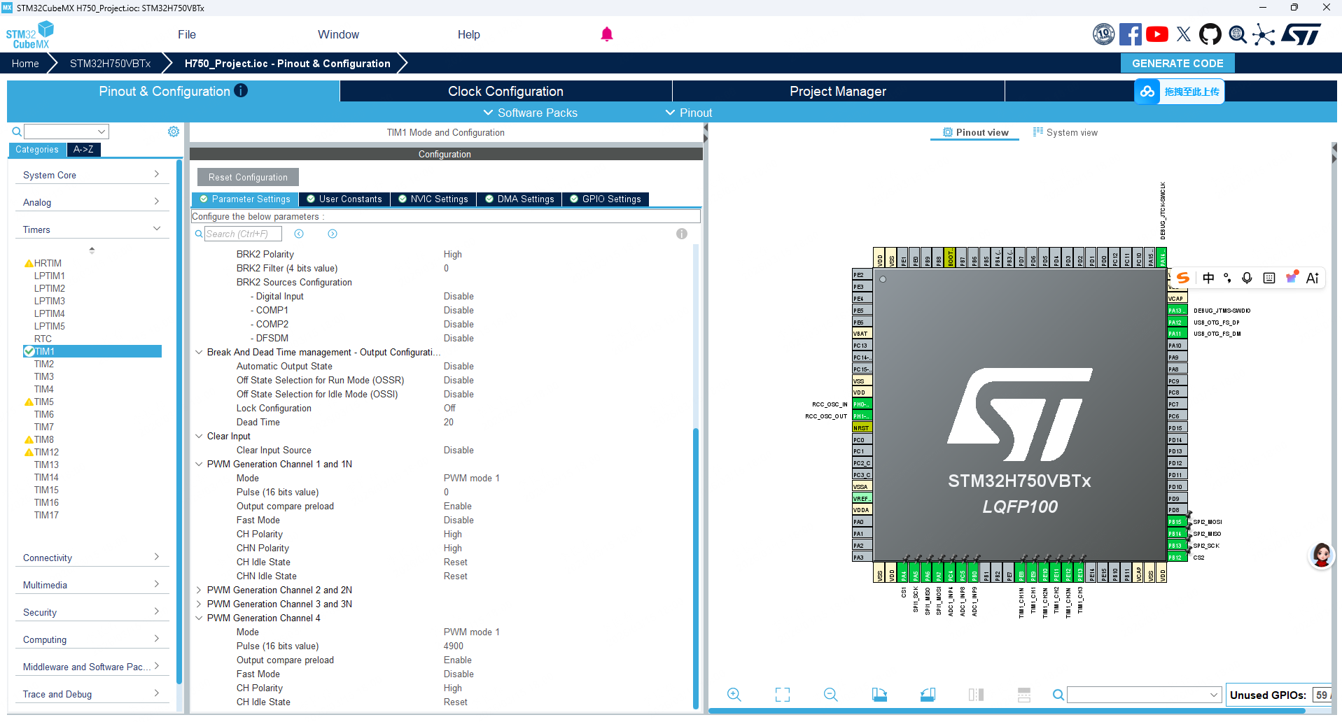
此外还需要添加下面这段代码来开启PWM
  /* USER CODE BEGIN TIM1_Init 2 */
  HAL_TIM_PWM_Start(&htim1,TIM_CHANNEL_1);
  HAL_TIM_PWM_Start(&htim1,TIM_CHANNEL_2);
  HAL_TIM_PWM_Start(&htim1,TIM_CHANNEL_3);
  HAL_TIMEx_PWMN_Start(&htim1,TIM_CHANNEL_1); // CH1N
  HAL_TIMEx_PWMN_Start(&htim1,TIM_CHANNEL_2); // CH2N
  HAL_TIMEx_PWMN_Start(&htim1,TIM_CHANNEL_3); // CH3N
  HAL_TIM_PWM_Start(&htim1,TIM_CHANNEL_4); // 启动CH4通道,确保CC4事件正常产生
  /* USER CODE END TIM1_Init 2 */
ADC
下面只简单介绍,读者如果有不清楚的可以吧CubeMX的配置图片发给AI。
| 配置项 | 值 | 作用 |
|---|---|---|
Enable Injected Conversions |
Enable | 使用高优先级注入通道,支持硬件触发、单次精准采样 |
Number Of Conversions |
3 | 一次触发采 3 路信号(如 Iu.Iv.Iw),满足 FOC 多变量需求 |
External Trigger Source |
TIM1_CC4 | 绑定定时器比较事件,在 PWM 峰值(CCR4=4900@ARR=5000)触发采样 |
Trigger Edge |
Rising | 确保TIM CH4每周期仅触发一次,避免误采 |
Injected Queue |
Disable | 简化逻辑,每次触发固定执行 Rank1~3 序列 |
Rank1: Channel 4, Sampling Time = 64.5 |
— | 第一路采样通道 + 合理采样时长(兼顾精度与速度) |
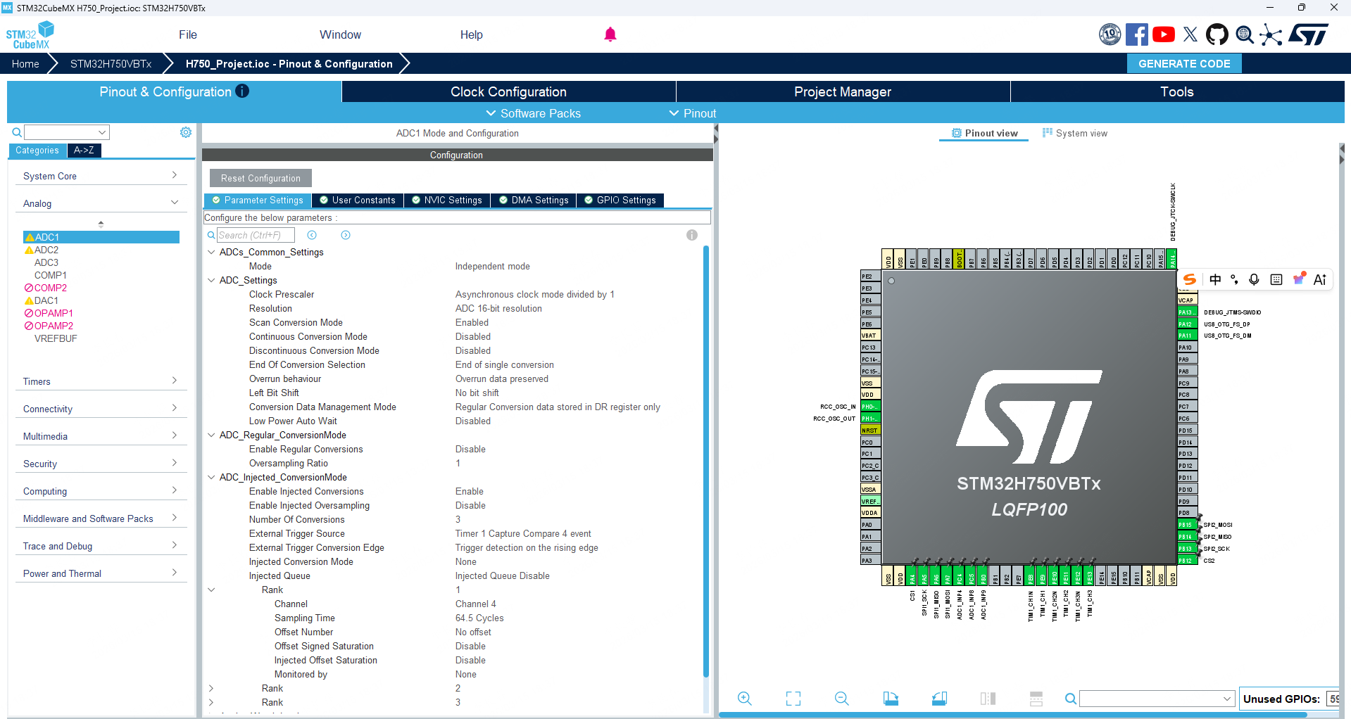
此外还要使能ADC中断,电机相关的所有代码都会在ADC采样完成后触发的中断中运行,这样能保证最高的实时性。

还需要添加下面这些代码打开ADC注入组中断。
  __HAL_ADC_ENABLE_IT(&hadc1, ADC_IT_JEOC);
  HAL_ADCEx_InjectedStart_IT(&hadc1);
电流采样
低端采样
硬件
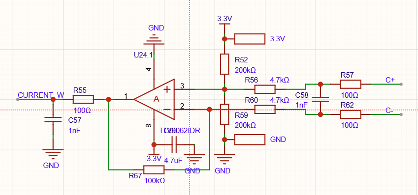
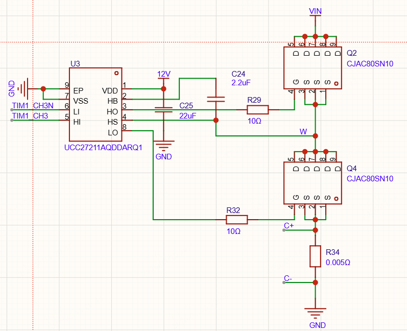
这是一个经典的电机低端电流采样电路。左边是一个带1.65V直流偏置的差分放大电路,放大倍数为100/4.7=21.27659574468085。右边为经典的半桥驱动电路下桥臂导通时,电流流过0.005Ω的电阻,产生压降,经过左边的电路放大后连接到MCU进行ADC采样。
模拟电压=ADC采样值(16位)/65536
电流=(模拟电压-1.65V)/21.27659574468085/0.005
由此可以计算出电流。
软件
ADC零点校准,笔者解释下为什么要这样处理。理想状态下在流过电机的电流为0时,运放的输出应为1.65V,但是实际采样可能是1.67V、1.63V 等等。这是由于运放电路中的电阻本身就有误差、还有运算放大器的误差(输入失调电压)。所以要测出电流为0时的实际电压,这个电压通常接近1.65V。
/**
 * @brief  ADC零点校准(电机上电静止时调用1次)
 * @note   采样100次求平均,消除硬件偏移
 */
void ADC_Calibrate_Zero(void)
{
  uint32_t sum_u = 0, sum_v = 0, sum_w = 0;
  uint8_t i;

  // 轮询采样100次
  for(i = 0; i < 100; i++)
  {
    // 启动注入转换(TIM1 CC4硬件触发)
    HAL_ADCEx_InjectedStart(&hadc1);
    // 等待转换完成(超时10ms)
    if(HAL_ADCEx_InjectedPollForConversion(&hadc1, 10) == HAL_OK)
    {
      sum_u += HAL_ADCEx_InjectedGetValue(&hadc1, ADC_INJECTED_RANK_1);
      sum_v += HAL_ADCEx_InjectedGetValue(&hadc1, ADC_INJECTED_RANK_2);
      sum_w += HAL_ADCEx_InjectedGetValue(&hadc1, ADC_INJECTED_RANK_3);
    }
    HAL_Delay(1);
  }

  // 计算零点(平均值)
  adc_zero_u = sum_u / 100;
  adc_zero_v = sum_v / 100;
  adc_zero_w = sum_w / 100;

  // 调试输出(可选)
  // printf("ADC零点校准完成:U=%lu, V=%lu, W=%lu\r\n", adc_zero_u, adc_zero_v, adc_zero_w);
}
将MCU的采集到ADC值转换成电流。
/**
 * @brief  原始采样值转实际电流(A)
 * @param  adc_val: 原始采样值
 * @param  zero_val: 零点值
 * @retval 实际电流值(A)
 * @note   需根据硬件参数调整:采样电阻0.005Ω,运放增益21.27659574468085,参考电压3.3V
 */
float ADC_Raw_To_Current(uint16_t adc_val, uint16_t zero_val)
{
  #define ADC_REF_VOLTAGE 3.3f    // ADC参考电压
  #define ADC_MAX_VALUE   65535.0f// 16位ADC最大值
  #define SAMPLE_RES      0.005f    // 采样电阻(Ω)
  #define AMP_GAIN        21.27659574468085f    // 运放增益

  // 计算采样电压:(采样值-零点) * 参考电压 / ADC最大值
  float voltage = (zero_val - adc_val) * ADC_REF_VOLTAGE / ADC_MAX_VALUE;
  // 计算实际电流:电压 / (采样电阻 * 运放增益)
  float current = voltage / (SAMPLE_RES * AMP_GAIN);

  return current;
}
电机控制算法的开头这样调用就可以获取实际的电流值了,之后就可以作为参数输入Clark变换。
    adc_iu_raw = HAL_ADCEx_InjectedGetValue(&hadc1, ADC_INJECTED_RANK_1);
    adc_iv_raw = HAL_ADCEx_InjectedGetValue(&hadc1, ADC_INJECTED_RANK_3);
    adc_iw_raw = HAL_ADCEx_InjectedGetValue(&hadc1, ADC_INJECTED_RANK_2);
    adc_iu = ADC_Raw_To_Current(adc_iu_raw, adc_zero_u);
    adc_iv = ADC_Raw_To_Current(adc_iv_raw, adc_zero_v);
    adc_iw = ADC_Raw_To_Current(adc_iw_raw, adc_zero_w);
相线采样
在PWM频率较高的时候使用。
未完待续(有时间再更新)。
高端采样
集成了前面两种采样的全部缺点,不建议使用。
电机控制算法
Clark变换
/**
 * @brief  Clark变换:三相电流(IU/IV/IW) → 两相静止坐标系(Iα/Iβ)
 * @note   利用IU+IV+IW=0简化计算,减少运算量
 */
void Clark_Transform(float IU, float IV, float IW, float *Ialpha, float *Ibeta)
{
  const float cos_2PI_BY_3 = cosf(2.0f * M_PI / 3.0f); // cos(120°)
  const float sin_2PI_BY_3 = sinf(2.0f * M_PI / 3.0f); // sin(120°)
  // 预计算常量
  *Ialpha = IU + cos_2PI_BY_3 * IV + cos_2PI_BY_3 * IW;
  *Ibeta = sin_2PI_BY_3 * IV -  sin_2PI_BY_3 * IW;
}
Park变换
/**
 * @brief  Park变换:两相静止坐标系(Iα/Iβ) → 两相旋转坐标系(Id/Iq)
 * @param  theta: 电机电角度(rad)
 */
void Park_Transform(float Ialpha, float Ibeta, float theta, float *Id, float *Iq)
{
  float sin_theta = sinf(theta);
  float cos_theta = cosf(theta);

  *Id = Ialpha * cos_theta + Ibeta * sin_theta;
  *Iq = -Ialpha * sin_theta + Ibeta * cos_theta;
}
反Park变换
/**
 * @brief 反Park变换 (Inverse Park Transform)
 * @param Id: d轴分量 (float)
 * @param Iq: q轴分量 (float)
 * @param theta: 电角度 (弧度制, rad)
 * @param Ialpha: 输出 alpha轴分量指针
 * @param Ibeta: 输出 beta轴分量指针
 *
 * @note: 适用于STM32 FPU (Cortex-M4/M7),单精度浮点运算
 */
void InvPark_Transform(float Id, float Iq, float theta, float *Ialpha, float *Ibeta)
{
    // 1. 计算三角函数 (硬件FPU会加速此过程)
    // 如果theta范围未限制在 [0, 2PI],建议先做归一化以提高sin/cos精度
    float sin_theta = sinf(theta);
    float cos_theta = cosf(theta);

    // 2. 执行矩阵乘法
    // I_alpha = Id * cos(theta) - Iq * sin(theta)
    // I_beta  = Id * sin(theta) + Iq * cos(theta)

    // 利用中间变量减少重复读取,方便编译器优化为乘加指令 (VMLA.F32)
    float cos_term = cos_theta;
    float sin_term = sin_theta;

    *Ialpha = (Id * cos_term) - (Iq * sin_term);
    *Ibeta  = (Id * sin_term) + (Iq * cos_term);
}
SVPWM(基于占空比)
SVPWM部分,笔者参考了github开源的代码
/**
 * @brief svm Space vector modulation. Magnitude must not be larger than sqrt(3)/2, or 0.866 to avoid overmodulation.
 *        See https://github.com/vedderb/bldc/pull/372#issuecomment-962499623 for a full description.
 * @param alpha voltage
 * @param beta Park transformed and normalized voltage
 * @param PWMFullDutyCycle is the peak value of the PWM counter.
 * @param tAout PWM duty cycle phase A (0 = off all of the time, PWMFullDutyCycle = on all of the time)
 * @param tBout PWM duty cycle phase B
 * @param tCout PWM duty cycle phase C
 */
void foc_svm(float alpha, float beta, float max_mod, uint32_t PWMFullDutyCycle,
				uint32_t* tAout, uint32_t* tBout, uint32_t* tCout, uint32_t *svm_sector) {
	uint32_t sector;

	if (beta >= 0.0f) {
		if (alpha >= 0.0f) {
			//quadrant I
			if (ONE_BY_SQRT3 * beta > alpha) {
				sector = 2;
			} else {
				sector = 1;
			}
		} else {
			//quadrant II
			if (-ONE_BY_SQRT3 * beta > alpha) {
				sector = 3;
			} else {
				sector = 2;
			}
		}
	} else {
		if (alpha >= 0.0f) {
			//quadrant IV5
			if (-ONE_BY_SQRT3 * beta > alpha) {
				sector = 5;
			} else {
				sector = 6;
			}
		} else {
			//quadrant III
			if (ONE_BY_SQRT3 * beta > alpha) {
				sector = 4;
			} else {
				sector = 5;
			}
		}
	}

	// PWM timings
	int tA, tB, tC;

	switch (sector) {

	// sector 1-2
	case 1: {
		// Vector on-times
		int t1 = (alpha - ONE_BY_SQRT3 * beta) * PWMFullDutyCycle;
		int t2 = (TWO_BY_SQRT3 * beta) * PWMFullDutyCycle;

		// PWM timings
		tA = (PWMFullDutyCycle + t1 + t2) / 2;
		tB = tA - t1;
		tC = tB - t2;

		break;
	}

	// sector 2-3
	case 2: {
		// Vector on-times
		int t2 = (alpha + ONE_BY_SQRT3 * beta) * PWMFullDutyCycle;
		int t3 = (-alpha + ONE_BY_SQRT3 * beta) * PWMFullDutyCycle;

		// PWM timings
		tB = (PWMFullDutyCycle + t2 + t3) / 2;
		tA = tB - t3;
		tC = tA - t2;

		break;
	}

	// sector 3-4
	case 3: {
		// Vector on-times
		int t3 = (TWO_BY_SQRT3 * beta) * PWMFullDutyCycle;
		int t4 = (-alpha - ONE_BY_SQRT3 * beta) * PWMFullDutyCycle;

		// PWM timings
		tB = (PWMFullDutyCycle + t3 + t4) / 2;
		tC = tB - t3;
		tA = tC - t4;

		break;
	}

	// sector 4-5
	case 4: {
		// Vector on-times
		int t4 = (-alpha + ONE_BY_SQRT3 * beta) * PWMFullDutyCycle;
		int t5 = (-TWO_BY_SQRT3 * beta) * PWMFullDutyCycle;

		// PWM timings
		tC = (PWMFullDutyCycle + t4 + t5) / 2;
		tB = tC - t5;
		tA = tB - t4;

		break;
	}

	// sector 5-6
	case 5: {
		// Vector on-times
		int t5 = (-alpha - ONE_BY_SQRT3 * beta) * PWMFullDutyCycle;
		int t6 = (alpha - ONE_BY_SQRT3 * beta) * PWMFullDutyCycle;

		// PWM timings
		tC = (PWMFullDutyCycle + t5 + t6) / 2;
		tA = tC - t5;
		tB = tA - t6;

		break;
	}

	// sector 6-1
	case 6: {
		// Vector on-times
		int t6 = (-TWO_BY_SQRT3 * beta) * PWMFullDutyCycle;
		int t1 = (alpha + ONE_BY_SQRT3 * beta) * PWMFullDutyCycle;

		// PWM timings
		tA = (PWMFullDutyCycle + t6 + t1) / 2;
		tC = tA - t1;
		tB = tC - t6;

		break;
	}
	}

	int t_max = PWMFullDutyCycle * (1.0 - (1.0 - max_mod) * 0.5);
	utils_truncate_number_int(&tA, 0, t_max);
	utils_truncate_number_int(&tB, 0, t_max);
	utils_truncate_number_int(&tC, 0, t_max);

	*tAout = tA;
	*tBout = tB;
	*tCout = tC;
	*svm_sector = sector;
}
SVPWM(基于电压)
/**
 * @brief  SVPWM计算:根据alpha/beta电压指令计算三相PWM占空比,
 *         反Park变换输入Uq(相线电压峰峰值,最大为母线电压)得到alpha/beta电压,
 *         根据实际母线电压调整max_voltage参数
 * @param  alpha: d轴分量
 * @param  beta: q轴分量
 * @param  max_voltage: 最大电压(母线电压)
 * @param  PWMFullDutyCycle: PWM全周期计数值(定死时钟和PWM频率下为常数)
 * @param  tUout: U相输出CCR值指针
 * @param  tVout: V相输出CCR值指针
 * @param  tWout: W相输出CCR值指针
 * @param  svm_sector: SVM扇区
 */
void foc_svm_voltage(float alpha, float beta, float max_voltage, uint32_t PWMFullDutyCycle,
				uint32_t* tUout, uint32_t* tVout, uint32_t* tWout, uint32_t *svm_sector) {
	uint32_t sector;
  const float ONE_BY_SQRT3 = 0.5773502691896258f; // 1/sqrt(3)
  const float TWO_BY_SQRT3 = 1.1547005383792517f; // 2/sqrt(3)
  alpha = alpha/max_voltage*0.75f;
  beta = beta/max_voltage*0.75f;
	if (beta >= 0.0f) {
		if (alpha >= 0.0f) {
			//quadrant I
			if (ONE_BY_SQRT3 * beta > alpha) {
				sector = 2;
			} else {
				sector = 1;
			}
		} else {
			//quadrant II
			if (-ONE_BY_SQRT3 * beta > alpha) {
				sector = 3;
			} else {
				sector = 2;
			}
		}
	} else {
		if (alpha >= 0.0f) {
			//quadrant IV5
			if (-ONE_BY_SQRT3 * beta > alpha) {
				sector = 5;
			} else {
				sector = 6;
			}
		} else {
			//quadrant III
			if (ONE_BY_SQRT3 * beta > alpha) {
				sector = 4;
			} else {
				sector = 5;
			}
		}
	}

	// PWM timings
	int tA, tB, tC;

	switch (sector) {

	// sector 1-2
	case 1: {
		// Vector on-times
		int t1 = (alpha - ONE_BY_SQRT3 * beta) * PWMFullDutyCycle;
		int t2 = (TWO_BY_SQRT3 * beta) * PWMFullDutyCycle;

		// PWM timings
		tA = (PWMFullDutyCycle + t1 + t2) / 2;
		tB = tA - t1;
		tC = tB - t2;

		break;
	}

	// sector 2-3
	case 2: {
		// Vector on-times
		int t2 = (alpha + ONE_BY_SQRT3 * beta) * PWMFullDutyCycle;
		int t3 = (-alpha + ONE_BY_SQRT3 * beta) * PWMFullDutyCycle;

		// PWM timings
		tB = (PWMFullDutyCycle + t2 + t3) / 2;
		tA = tB - t3;
		tC = tA - t2;

		break;
	}

	// sector 3-4
	case 3: {
		// Vector on-times
		int t3 = (TWO_BY_SQRT3 * beta) * PWMFullDutyCycle;
		int t4 = (-alpha - ONE_BY_SQRT3 * beta) * PWMFullDutyCycle;

		// PWM timings
		tB = (PWMFullDutyCycle + t3 + t4) / 2;
		tC = tB - t3;
		tA = tC - t4;

		break;
	}

	// sector 4-5
	case 4: {
		// Vector on-times
		int t4 = (-alpha + ONE_BY_SQRT3 * beta) * PWMFullDutyCycle;
		int t5 = (-TWO_BY_SQRT3 * beta) * PWMFullDutyCycle;

		// PWM timings
		tC = (PWMFullDutyCycle + t4 + t5) / 2;
		tB = tC - t5;
		tA = tB - t4;

		break;
	}

	// sector 5-6
	case 5: {
		// Vector on-times
		int t5 = (-alpha - ONE_BY_SQRT3 * beta) * PWMFullDutyCycle;
		int t6 = (alpha - ONE_BY_SQRT3 * beta) * PWMFullDutyCycle;

		// PWM timings
		tC = (PWMFullDutyCycle + t5 + t6) / 2;
		tA = tC - t5;
		tB = tA - t6;

		break;
	}
示例代码
简单解释一此示例代码:
该函数是基于STM32 H7的FOC核心中断服务程序,利用ADC注入组在PWM中心时刻(下桥臂导通期)自动触发低端电流采样,确保获取无噪声的三相电流;中断内依次执行Clarke/Park变换将交流电流解耦为直流量(Id/Iq),经控制算法(如PID)生成电压指令后,再通过反Park变换与SVPWM算法计算出新的三相占空比,并直接更新定时器寄存器,从而在微秒级内完成从“电流感知”到“磁场控制”的完整闭环,实现电机的高性能精准驱动。
/**
* @brief ADC注入转换完成回调函数
* @note 需启用ADC中断,在stm32h7xx_it.c中实现ADC_IRQHandler
*/
void HAL_ADCEx_InjectedConvCpltCallback(ADC_HandleTypeDef* hadc)
{
if(hadc->Instance == ADC1)
{
// 1. 读取采样值
adc_iu_raw = HAL_ADCEx_InjectedGetValue(&hadc1, ADC_INJECTED_RANK_1);
adc_iv_raw = HAL_ADCEx_InjectedGetValue(&hadc1, ADC_INJECTED_RANK_3);
adc_iw_raw = HAL_ADCEx_InjectedGetValue(&hadc1, ADC_INJECTED_RANK_2);
adc_iu = ADC_Raw_To_Current(adc_iu_raw, adc_zero_u);
adc_iv = ADC_Raw_To_Current(adc_iv_raw, adc_zero_v);
adc_iw = ADC_Raw_To_Current(adc_iw_raw, adc_zero_w);
// 2. 根据编码器角度,计算出转子的电角度(temp_angle)。
read_radian_angle(&angle);
temp_angle = (angle)*11.0f - angle_error;
temp_angle = fmod(temp_angle, M_PI * 2);
if (temp_angle < 0.0f) {
temp_angle += M_PI * 2;
}
// 3. Clark变换 -> Park变换 -> 反Park变换,得到alpha/beta电压指令
Clark_Transform(adc_iu, adc_iv, adc_iw, &Ialpha, &Ibeta);
// 4. Park变换 -> 反Park变换,得到alpha/beta电压指令
Park_Transform(Ialpha, Ibeta, temp_angle, &Id, &Iq);
// 5. 反Park变换,得到alpha/beta电压指令
InvPark_Transform(mod_d, mod_q, temp_angle, &alpha, &beta);
// 6. SVM计算PWM占空比
foc_svm(alpha, beta, 0.866f, 5000, &TA, &TB, &TC, §or);
// 7. 更新PWM寄存器
TIM1->CCR1 = TA;
TIM1->CCR2 = TB;
TIM1->CCR3 = TC;
}
}下面为一个使用示例
void motor_calculate()
{
// 1. 读取采样值
adc_iu_raw = HAL_ADCEx_InjectedGetValue(&hadc1, ADC_INJECTED_RANK_1);
adc_iv_raw = HAL_ADCEx_InjectedGetValue(&hadc1, ADC_INJECTED_RANK_3);
adc_iw_raw = HAL_ADCEx_InjectedGetValue(&hadc1, ADC_INJECTED_RANK_2);
adc_voltage = HAL_ADCEx_InjectedGetValue(&hadc1, ADC_INJECTED_RANK_4);
VBus = adc_voltage * 3.3f / 65535.0f * 21.0f; // 电压分压比为21:1
adc_iu = ADC_Raw_To_Current(adc_iu_raw, adc_zero_u);
adc_iv = ADC_Raw_To_Current(adc_iv_raw, adc_zero_v);
adc_iw = ADC_Raw_To_Current(adc_iw_raw, adc_zero_w);
// 2. 根据编码器角度,计算出转子的电角度(temp_angle)。
read_radian_angle(&angle);
temp_angle = (angle)*7.0f - angle_error;
temp_angle = fmod(temp_angle, M_PI * 2);
if (temp_angle < 0.0f) {
temp_angle += M_PI * 2;
}
// static float temp_angle = 0.0f;
// temp_angle +=0.0001f;
// if (temp_angle>M_PI*2) {
// temp_angle -= M_PI*2;
// }
// 3. Clark变换 -> Park变换 -> 反Park变换,得到alpha/beta电压指令
Clark_Transform(adc_iu, adc_iv, adc_iw, &Ialpha, &Ibeta);
// 4. Park变换 -> 反Park变换,得到alpha/beta电压指令
Park_Transform(Ialpha, Ibeta, temp_angle, &Id, &Iq);
// 5. 反Park变换,得到alpha/beta电压指令
mod_q = 1.0f; // 设定q轴电流指令,保持恒定
InvPark_Transform(mod_d, mod_q, temp_angle, &alpha, &beta);
// 6. SVM计算PWM占空比
foc_svm_voltage(alpha, beta, VBus, 5000, &TA, &TB, &TC, §or);
// 7. 更新PWM寄存器
TIM1->CCR1 = TA;
TIM1->CCR2 = TB;
TIM1->CCR3 = TC;
}未完待续。

智能硬件社区聚焦AI智能硬件技术生态,汇聚嵌入式AI、物联网硬件开发者,打造交流分享平台,同步全国赛事资讯、开展 OPC 核心人才招募,助力技术落地与开发者成长。
更多推荐
 7
7 0
0- 0


 已为社区贡献1条内容

所有评论(0)