STM32CubeMX配置串口中断数据发送(四)
一、实验目的
当前有STM32L431ZET6开发板,电脑,数据线,想以USART1串口中断的方式通过电脑给开发板发生数据或字符串并且开发板收到数据后打印出来,使用CUBEMX+HAL库配置。
二、STM32CubeMX配置步骤
1. 创建新工程
打开STM32CubeMX,选择芯片型号:STM32F407ZET6
2. 配置RCC(时钟)
-
Pinout & Configuration → System Core → RCC
-
High Speed Clock (HSE):选择
Crystal/Ceramic Resonator(使用外部晶振)
3. 配置USART1
-
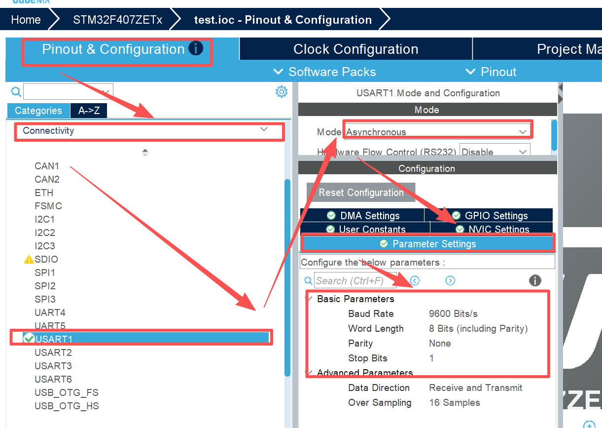
Pinout & Configuration → Connectivity → USART1
-
Mode:选择
Asynchronous(异步通信模式) -
参数配置:
text
Baud Rate: 9600    (波特率,与电脑串口助手一致)
Word Length: 8 Bits    (数据位)
Parity: None           (无校验位)
Stop Bits: 1           (停止位)
Data Direction: Receive and Transmit (收发使能)
-
NVIC Settings 选项卡:
text
☑ USART1 global interrupt (勾选,使能串口中断)
-
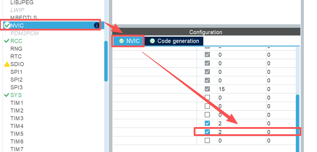
优先级可根据需要设置(如抢占优先级2,子优先级0)
-
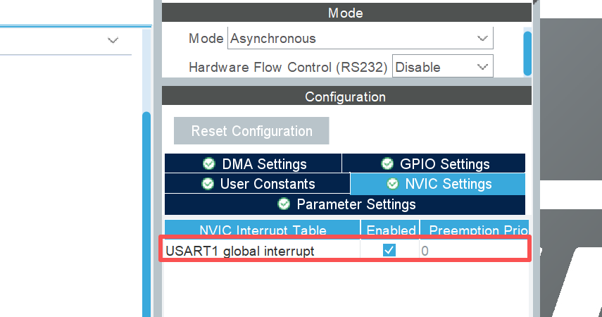
注意:NVIC Settings抢占优先级在这里改不了,需要到NVIC中改
-
确认引脚映射:(这里不需要操作,只要看PA9,PA10引脚变绿没有)
-
USART1_TX → PA9
-
USART1_RX → PA10
-

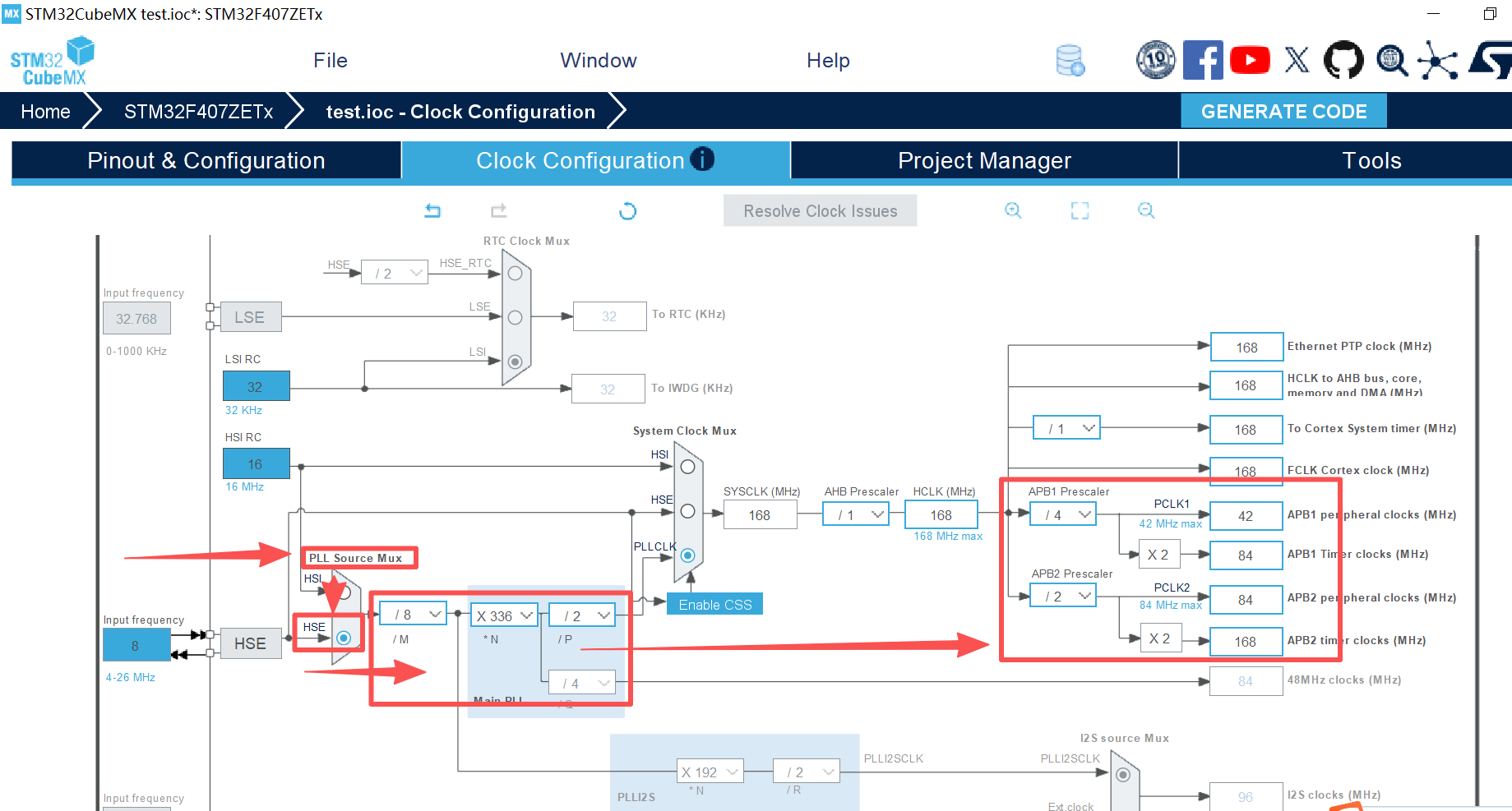
4. 配置时钟树(Clock Configuration)
-
外部晶振设为8MHz
-
配置系统时钟为 168MHz(STM32F407最高主频)
-
确保USART1时钟源正确
时钟树相关参数配置如下:
5. 生成代码
-
Project Manager → Project:填写项目名称、路径
-
Toolchain/IDE:选择
MDK-ARM(Keil)或STM32CubeIDE -
点击 GENERATE CODE 生成工程
三、HAL库代码实现
1. 在 main.c 中添加全局变量
在 /* USER CODE BEGIN PV */ 区域添加:
c
/* USER CODE BEGIN PV */
uint8_t rx_buffer;  // 单字节接收缓冲区
/* USER CODE END PV */
2. 包含头文件
在 /* USER CODE BEGIN Includes */ 区域添加:
/* USER CODE BEGIN Includes */
#include <stdio.h>
#include <string.h>
/* USER CODE END Includes */
3. 在主函数中初始化串口接收
在 /* USER CODE BEGIN 2 */ 区域添加:
c
/* USER CODE BEGIN 2 */
HAL_UART_Receive_IT(&huart1, &rx_buffer, 1);  // 启动中断接收
printf("UART Loopback Test Started\r\n");      // 可选,测试发送

/* USER CODE END 2 */
4. 重定义printf函数
在 /* USER CODE BEGIN 1 */ 区域添加:
c
/* USER CODE BEGIN 1 */
// 重定义printf函数,使其通过串口1输出
int fputc(int ch, FILE *f)
{
    HAL_UART_Transmit(&huart1, (uint8_t *)&ch, 1, 0xFFFF);
    return ch;
}

// 重定义getchar函数,接收串口数据
int fgetc(FILE *f)
{
    uint8_t ch = 0;
    HAL_UART_Receive(&huart1, &ch, 1, 0xFFFF);
    return ch;
}
/* USER CODE END 1 */
5. 添加串口接收中断回调函数
在 /* USER CODE BEGIN 4 */ 区域添加:
c
/* USER CODE BEGIN 4 */
void HAL_UART_RxCpltCallback(UART_HandleTypeDef *huart)
{
    if(huart->Instance == USART1)
    {
        // 收到什么就发回什么(回显)
        HAL_UART_Transmit(&huart1, &rx_buffer, 1, 0xFFFF);
        // 重新开启接收中断(必须!)
        HAL_UART_Receive_IT(&huart1, &rx_buffer, 1);
    }
}

/* USER CODE END 4 */
6. 主循环中处理接收到的数据
在 /* USER CODE BEGIN 3 */ 区域不写:
c
  /* Infinite loop */
  /* USER CODE BEGIN WHILE */
  while (1)
  {
    /* USER CODE END WHILE */

    /* USER CODE BEGIN 3 */


  }
  /* USER CODE END 3 */
四、Keil工程设置(重要!)
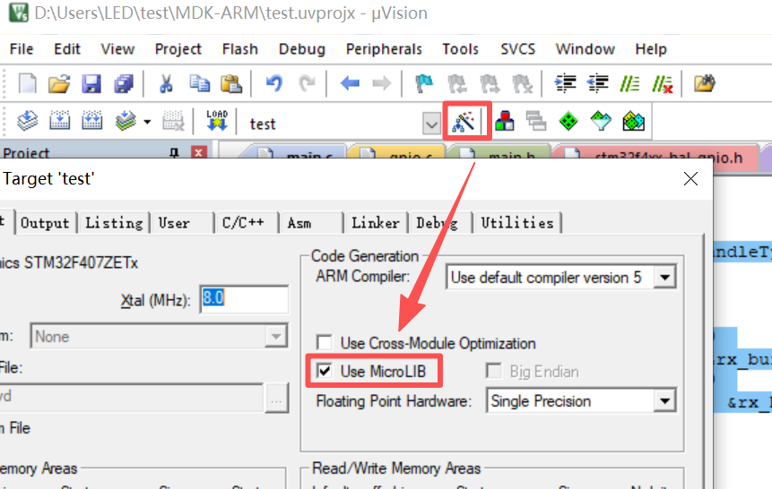
勾选使用MicroLIB
-
点击魔术棒图标(Options for Target)
-
选择 Target 选项卡
-
在 Code Generation 中勾选 Use MicroLIB
-
这样才能正常使用printf重定向
五、硬件连接与测试
1. 硬件连接
| 开发板引脚 | 连接目标 | 说明 |
|---|---|---|
| PA9 (USART1_TX) | USB转TTL的RX | 开发板发送,电脑接收 |
| PA10 (USART1_RX) | USB转TTL的TX | 电脑发送,开发板接收 |
| GND | USB转TTL的GND | 共地 |
2. 电脑端设置
-
使用串口调试助手(如SSCOM、XCOM、Putty等)
-
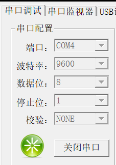
参数设置与CubeMX一致:
text
波特率:9600
数据位:8
停止位:1
校验位:None如下:
-
打开对应串口号
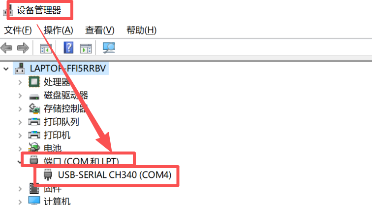
端口第一次使用需要先安装CH340完成后在设备管理器中查看端口号
3. 测试效果
-
开发板上电后,串口助手会收到启动信息
-
在串口助手中发送字符串(如 "Hello STM32"),然后按回车
-
开发板会回显
Received: Hello STM32
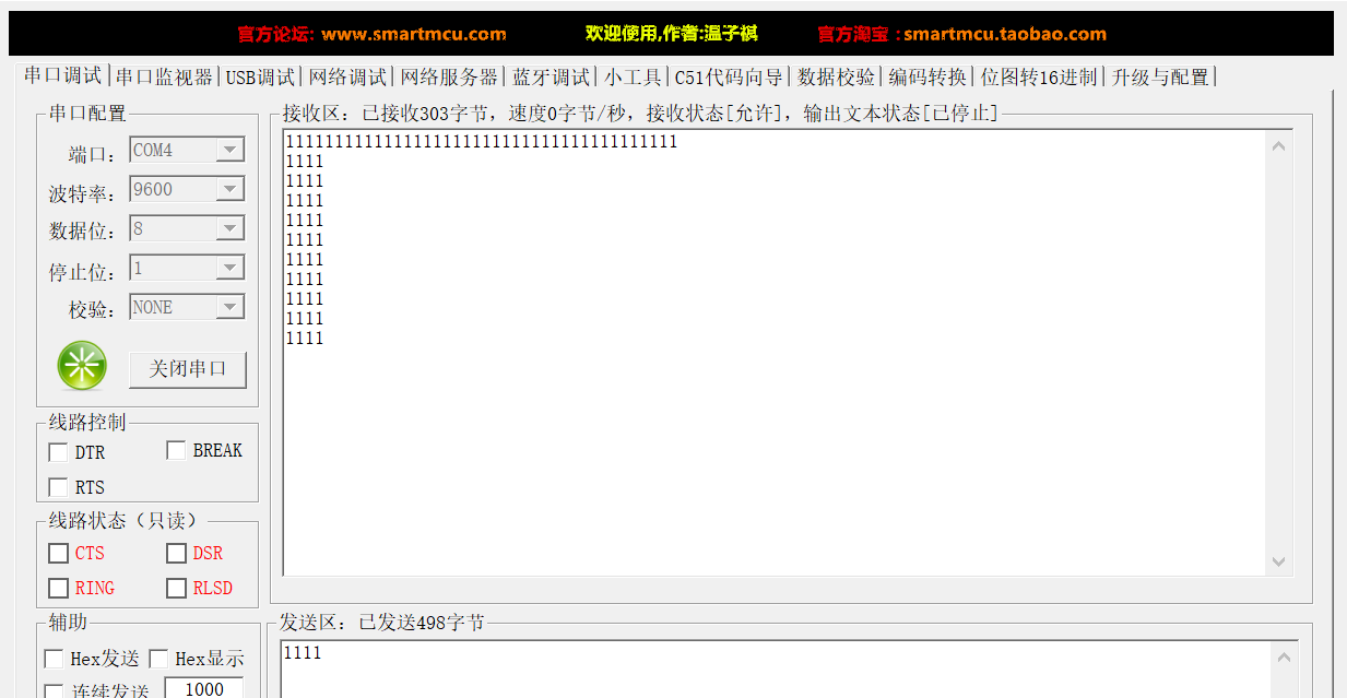
最终测试如下图:
六、完整代码结构参考
c
/* USER CODE BEGIN Header */
/**
  ******************************************************************************
  * @file           : main.c
  * @brief          : USART1 中断接收示例 - 收到字符串后打印
  ******************************************************************************
  */
/* USER CODE END Header */
/* Includes ------------------------------------------------------------------*/
#include "main.h"
#include "usart.h"
#include "gpio.h"

/* Private includes ----------------------------------------------------------*/
/* USER CODE BEGIN Includes */
#include <stdio.h>
#include <string.h>
/* USER CODE END Includes */

/* Private typedef -----------------------------------------------------------*/
/* USER CODE BEGIN PTD */

/* USER CODE END PTD */

/* Private define ------------------------------------------------------------*/
/* USER CODE BEGIN PD */

/* USER CODE END PD */

/* Private macro -------------------------------------------------------------*/
/* USER CODE BEGIN PM */

/* USER CODE END PM */

/* Private variables ---------------------------------------------------------*/

/* USER CODE BEGIN PV */
uint8_t rx_buffer;  // 单字节接收缓冲区
/* USER CODE END PV */

/* Private function prototypes -----------------------------------------------*/
void SystemClock_Config(void);
/* USER CODE BEGIN PFP */
/* Private user code ---------------------------------------------------------*/
/* USER CODE END PFP */

/* Private user code ---------------------------------------------------------*/
/* USER CODE BEGIN 0 */
// printf重定向函数
int fputc(int ch, FILE *f)
{
    HAL_UART_Transmit(&huart1, (uint8_t *)&ch, 1, 0xFFFF);
    return ch;
}
/* USER CODE END 0 */

/**
  * @brief  The application entry point.
  * @retval int
  */
int main(void)
{

  /* USER CODE BEGIN 1 */

  /* USER CODE END 1 */

  /* MCU Configuration--------------------------------------------------------*/

  /* Reset of all peripherals, Initializes the Flash interface and the Systick. */
  HAL_Init();

  /* USER CODE BEGIN Init */

  /* USER CODE END Init */

  /* Configure the system clock */
  SystemClock_Config();

  /* USER CODE BEGIN SysInit */

  /* USER CODE END SysInit */

  /* Initialize all configured peripherals */
  MX_GPIO_Init();
  MX_USART1_UART_Init();
  /* USER CODE BEGIN 2 */
    HAL_UART_Receive_IT(&huart1, &rx_buffer, 1);  // 启动中断接收
    printf("UART Loopback Test Started\r\n");      // 可选,测试发送
    // 打印启动信息

  /* USER CODE END 2 */

  /* Infinite loop */
  /* USER CODE BEGIN WHILE */
    while (1)
    {
    /* USER CODE END WHILE */

    /* USER CODE BEGIN 3 */
    }
  /* USER CODE END 3 */
}

/**
  * @brief System Clock Configuration
  * @retval None
  */
void SystemClock_Config(void)
{
  RCC_OscInitTypeDef RCC_OscInitStruct = {0};
  RCC_ClkInitTypeDef RCC_ClkInitStruct = {0};

  /** Configure the main internal regulator output voltage
  */
  __HAL_RCC_PWR_CLK_ENABLE();
  __HAL_PWR_VOLTAGESCALING_CONFIG(PWR_REGULATOR_VOLTAGE_SCALE1);

  /** Initializes the RCC Oscillators according to the specified parameters
  * in the RCC_OscInitTypeDef structure.
  */
  RCC_OscInitStruct.OscillatorType = RCC_OSCILLATORTYPE_HSE;
  RCC_OscInitStruct.HSEState = RCC_HSE_ON;
  RCC_OscInitStruct.PLL.PLLState = RCC_PLL_ON;
  RCC_OscInitStruct.PLL.PLLSource = RCC_PLLSOURCE_HSE;
  RCC_OscInitStruct.PLL.PLLM = 8;
  RCC_OscInitStruct.PLL.PLLN = 336;
  RCC_OscInitStruct.PLL.PLLP = RCC_PLLP_DIV2;
  RCC_OscInitStruct.PLL.PLLQ = 4;
  if (HAL_RCC_OscConfig(&RCC_OscInitStruct) != HAL_OK)
  {
    Error_Handler();
  }

  /** Initializes the CPU, AHB and APB buses clocks
  */
  RCC_ClkInitStruct.ClockType = RCC_CLOCKTYPE_HCLK|RCC_CLOCKTYPE_SYSCLK
                              |RCC_CLOCKTYPE_PCLK1|RCC_CLOCKTYPE_PCLK2;
  RCC_ClkInitStruct.SYSCLKSource = RCC_SYSCLKSOURCE_PLLCLK;
  RCC_ClkInitStruct.AHBCLKDivider = RCC_SYSCLK_DIV1;
  RCC_ClkInitStruct.APB1CLKDivider = RCC_HCLK_DIV4;
  RCC_ClkInitStruct.APB2CLKDivider = RCC_HCLK_DIV2;

  if (HAL_RCC_ClockConfig(&RCC_ClkInitStruct, FLASH_LATENCY_5) != HAL_OK)
  {
    Error_Handler();
  }
}

/* USER CODE BEGIN 4 */
void HAL_UART_RxCpltCallback(UART_HandleTypeDef *huart)
{
    if(huart->Instance == USART1)
    {
        // 收到什么就发回什么(回显)
        HAL_UART_Transmit(&huart1, &rx_buffer, 1, 0xFFFF);
        // 重新开启接收中断(必须!)
        HAL_UART_Receive_IT(&huart1, &rx_buffer, 1);
    }
}

/* USER CODE END 4 */

/**
  * @brief  This function is executed in case of error occurrence.
  * @retval None
  */
void Error_Handler(void)
{
  /* USER CODE BEGIN Error_Handler_Debug */
    /* User can add his own implementation to report the HAL error return state */
    __disable_irq();
    while (1)
    {
        // 错误时快速闪烁(如果有LED)
        // HAL_GPIO_TogglePin(LED_GPIO_Port, LED_Pin);
        // HAL_Delay(100);
    }
  /* USER CODE END Error_Handler_Debug */
}
#ifdef USE_FULL_ASSERT
/**
  * @brief  Reports the name of the source file and the source line number
  *         where the assert_param error has occurred.
  * @param  file: pointer to the source file name
  * @param  line: assert_param error line source number
  * @retval None
  */
void assert_failed(uint8_t *file, uint32_t line)
{
  /* USER CODE BEGIN 6 */
    /* User can add his own implementation to report the file name and line number */
    printf("Wrong parameters value: file %s on line %d\r\n", file, line);
  /* USER CODE END 6 */
}
#endif /* USE_FULL_ASSERT */

智能硬件社区聚焦AI智能硬件技术生态,汇聚嵌入式AI、物联网硬件开发者,打造交流分享平台,同步全国赛事资讯、开展 OPC 核心人才招募,助力技术落地与开发者成长。
更多推荐
 16
16 0
0- 0


 已为社区贡献12条内容

所有评论(0)