玩转 Xilinx 下载器(五)—— SmartLynq 拆机
SmartLynq 介绍
SmartLynq 盒子是用于编程和调试 Xilinx 设备的完整的一体化解决方案。该盒子包括以下功能:
-
支持高达40Mb/s的JTAG速率,电压范围为1.2V至3.3V。
-
提供以太网和USB主机端连接。
-
遵循行业标准,包括JTAG边界扫描IEEE标准1149.1-测试访问端口和边界扫描架构。
-
支持所有UltraScale™、UltraScale+™和7系列产品,以及 Zynq-7000 SoC 和 Zynq UltraScale+MPSoC。
-
通过设备的JTAG端口间接编程选定的串行外围接口(SPI)闪存或并行闪存设备。
-
提供3.3V 8位通用I/O(GPIO)端口。
-
针对 Xilinx Vivado 设计工具进行了优化。
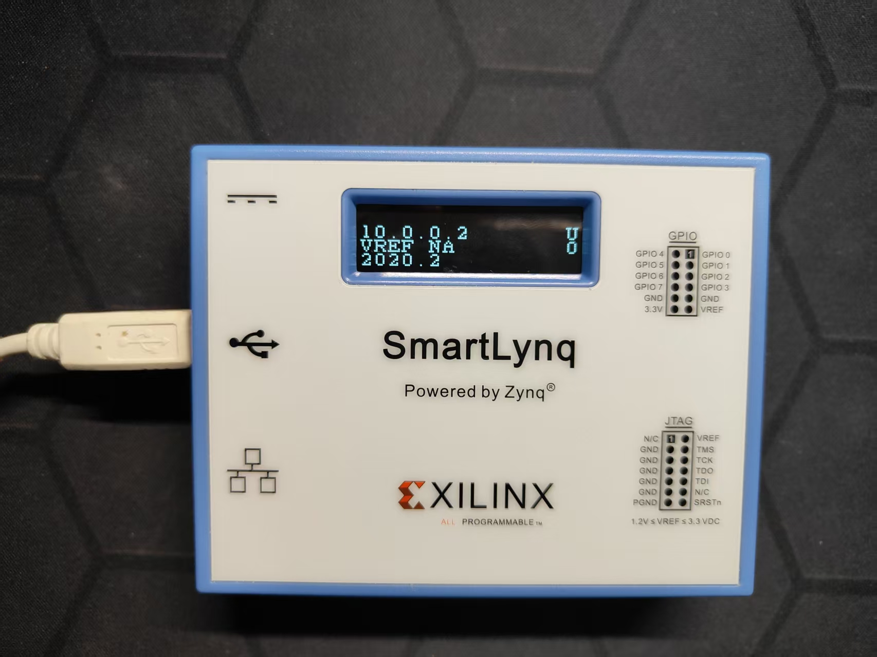
拆机
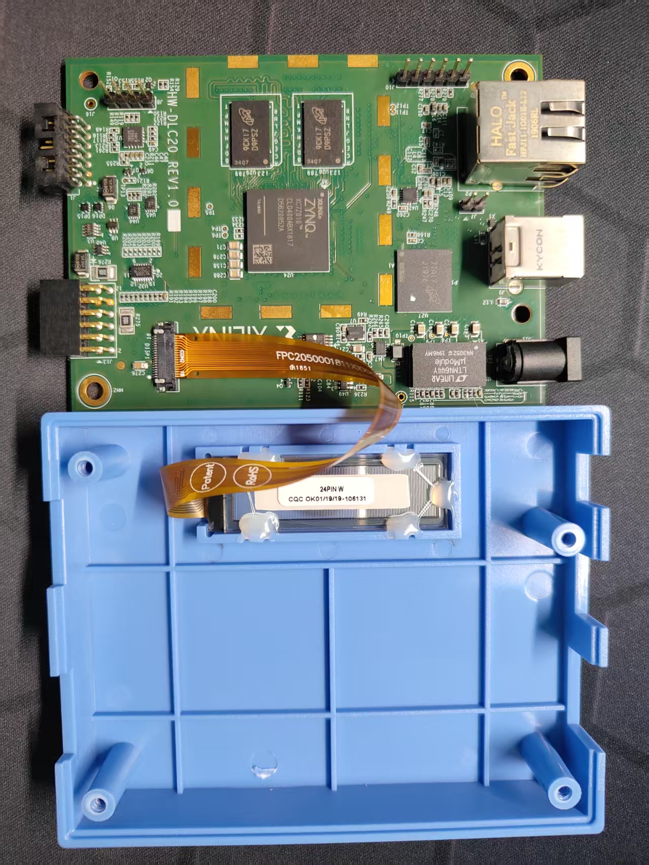
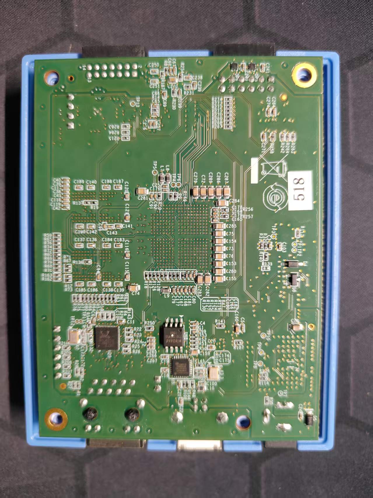
仅用四颗螺丝固定
主要芯片:
-
主芯片ZYNQ XC7Z010CLG400,双核Cortex-A9,PL
-
DDR3:Micron MT41K128M16JT-107:K,512MB
-
QSPI Flash: winbond 25Q128FWSQ,16MB
-
EMMC:MTFC4GACAJCN-1M WT,4GB
-
以太网 PHY: RTL8211E
-
USB PHY:SMSC USB3320C
还有一些电源芯片及电平转换芯片。
除了对外的一些接口,板子上还有三个插针座,J7/J8/J10,经分析分别是启动模式跳线、UART、JTAG 接口。分别定义如下:
J7 - Boot Mode,默认 QSPI 启动,跳线后为 JTAG Boot Mode。
J8 - UART
1-
2- TX
3-
4- GND
J10 - JTAG
1 - VREF
2 - GND
3 - TCK
4 - TMS
5 - TDI
6 - TDO
上电开机
接上UART上电开机,可以看到下面的 UART log 输出:
Finished init UART
Reboot status 400000
WDT STS 0
There should not be any DDR prints
Boot mode 1Using EMMC Boot
SD: rc= 0
FSBL SD E0100000
read base E0100000
DDR prints and access skipped
Multiboot Register: 0x0000C000
flash read base addr E0100000, image base 0
image move with partition number 0
Partition hdr for 0: CC0
--------- Header dump:
Image Word Len: 0003AAD0
Data Word Len: 0003AAD0
Partition Word Len: 0003AAD0
Load Addr: 00000000
Exec Addr: 00000000
Partition Start: 00005E50
Partition Attr: 00000020
Section Count: 00000001
Checksum: FFF49ECE
Partition Start 00000CC0, Partition Length 0003AAD0
Source addr 00017940, Load addr 00000000, Exec addr 00000000
**** Bitstream ****
PCAP:StatusReg = 0x40000A30
PCAP:device ready
PCAP register dump:
PCAP CTRL F8007000: 4C00E07F
PCAP LOCK F8007004: 0000001A
PCAP CONFIG F8007008: 00000508
PCAP ISR F800700C: 00020000
PCAP IMR F8007010: FFFFFFFF
PCAP STATUS F8007014: 40000A30
PCAP DMA SRC F8007018: FC001701
PCAP DMA DEST F800701C: 00040001
PCAP ROM SHADOW CTRL F8007028: FFFFFFFF
PCAP MBOOT F800702C: 0000C000
PCAP SW ID F8007030: 00000000
PCAP UNLOCK F8007034: 757BDF0D
PCAP MCTRL F8007080: 30800100
nand/sd access to address 17940 with length 6C0
nand/sd access to address 18000 with length 8000
nand/sd access to address 20000 with length 8000
nand/sd access to address 28000 with length 8000
nand/sd access to address 30000 with length 8000
nand/sd access to address 38000 with length 8000
nand/sd access to address 40000 with length 8000
nand/sd access to address 48000 with length 8000
nand/sd access to address 50000 with length 8000
nand/sd access to address 58000 with length 8000
nand/sd access to address 60000 with length 8000
nand/sd access to address 68000 with length 8000
nand/sd access to address 70000 with length 8000
nand/sd access to address 78000 with length 8000
nand/sd access to address 80000 with length 8000
nand/sd access to address 88000 with length 8000
nand/sd access to address 90000 with length 8000
nand/sd access to address 98000 with length 8000
nand/sd access to address A0000 with length 8000
nand/sd access to address A8000 with length 8000
nand/sd access to address B0000 with length 8000
nand/sd access to address B8000 with length 8000
nand/sd access to address C0000 with length 8000
nand/sd access to address C8000 with length 8000
nand/sd access to address D0000 with length 8000
nand/sd access to address D8000 with length 8000
nand/sd access to address E0000 with length 8000
nand/sd access to address E8000 with length 8000
nand/sd access to address F0000 with length 8000
nand/sd access to address F8000 with length 8000
nand/sd access to address 100000 with length 2480
Last transfer, 30, PCAP: Source = 16501
Last transfer, PCAP: destination = FFFFFFFF
DMA transfer done 50023004
Check FPGA config done....
FPGA config done 251658240, 50023004
Bitstream transfer time 79732D2
Bit stream download successful!
Partition hdr for 1: D00
Get next partition header
Partition hdr for 1: D00
--------- Next Header dump:
Image Word Len: 00000010
Data Word Len: 00000010
Partition Word Len: 00000010
Load Addr: 00100000
Exec Addr: 0020401C
Partition Start: 00040920
Partition Attr: 00000010
Section Count: 00000002
Checksum: FFCBB421
end of partition move, reboot status reg 1400000, Next partition 1
Hand off address 0
FSBL main: Skip partition
Multiboot Register: 0x0000C000
flash read base addr E0100000, image base 0
image move with partition number 1
Partition hdr for 1: D00
--------- Header dump:
Image Word Len: 00000010
Data Word Len: 00000010
Partition Word Len: 00000010
Load Addr: 00100000
Exec Addr: 0020401C
Partition Start: 00040920
Partition Attr: 00000010
Section Count: 00000002
Checksum: FFCBB421
Partition Start 00000D00, Partition Length 00000010
Source addr 00102480, Load addr 00100000, Exec addr 0020401C
Start transfer data into DDR
transfer time FFFFFCE4
Get next partition header
Partition hdr for 2: D40
Next partition header dump
Image Word Len: 0060BE0E
Data Word Len: 0060BE0E
Partition Word Len: 0060BE0E
Load Addr: 00200000
Exec Addr: 00000000
Partition Start: 00040930
Partition Attr: 00000010
Section Count: 00000000
Checksum: FEB9BA35
Partition Start 00000D00, Partition Length 0060BE0E
Source addr 001024C0, Load addr 00200000, Exec addr 0020401C
Start transfer data into DDR
transfer time FFFFFCE7
Get next partition header
Partition hdr for 3: D80
--------- Next Header dump:
Image Word Len: 00000000
Data Word Len: 00000000
Partition Word Len: 00000000
Load Addr: 00000000
Exec Addr: 00000000
Partition Start: 00000000
Partition Attr: 00000000
Section Count: 00000000
Checksum: FFFFFFFF
There are no more partitions to load
end of partition move, reboot status reg 2400000, Next partition 2
Hand off address 20401C
To handoff, End of main
Before handoff reboot status register 2400000
Reset USB...
FSBLStatus = 0x1
Loaded MAC Address from EEPROM
TCF 21:51:52.031: Cannot read config.ini: No such file or directory
TCF 21:51:52.031: property get ip-mac (default)
TCF 21:51:52.032: property get ip-gw-mac (default)
TCF 21:51:52.032: property get ip-address (default)
TCF 21:51:52.032: property get ip-gateway (default)
TCF 21:51:52.032: property get usb-mac (default)
TCF 21:51:52.032: property get usb-gw-mac (default)
TCF 21:51:52.032: property get usb-address (default)
Setting up Ethernet link.
ETH MAC address: 00:0a:35:04:83:45
TCF 21:51:52.032: property get jtag-clock-frequency (default)
TCF 21:51:52.032: property get jtag-clock-skew (default)
TCF 21:51:52.083: Cannot create HTTP server: Invalid transport name
USB serial number 867216741727-00837
USB: set interface: 0 1
USB: set interface: 1 1
USB: link up, DHCP 0
Interface un1 is up, IP address: 10.0.0.2
TCF 21:51:52.720: DHCPS: REQUEST 10.0.0.1
TCF 21:51:52.720: DHCPS: ACK 10.0.0.1
TCF 21:52:29.955: Node 000000FF, added jsn-XSC0-AAo1BINF0
TCF 21:52:29.955: jtagpoll: open port Xilinx/AAo1BINF0
TCF 21:53:21.930: Node 000000FF, added jsn-XSC0-AAo1BINF0
TCF 21:53:21.931: jtagpoll: open port Xilinx/AAo1BINF0
通过 Log 可以看出一些信息来,FSBL分为两级,首先由 QSPI boot,QSPI FSBL 做了很少的工作,初始化UART,驱动EMMC,加载 EMMC FSBL,然后由 EMMC FSBL 完成后续 boot,加载 PL bitstream,加载 App。FSBL boot app后没有看到任何 uboot信息,另外boot过程也非常快,看起来没有使用 Linux Kernel,具体是裸机还是RTOS还不确定。App 是 HW Server,网络接口交互TCF Protocol。
当然,7010 的 JTAG 接口是可用的,通过 JTAG 接口可以调试或读出固件来进一步分析。

智能硬件社区聚焦AI智能硬件技术生态,汇聚嵌入式AI、物联网硬件开发者,打造交流分享平台,同步全国赛事资讯、开展 OPC 核心人才招募,助力技术落地与开发者成长。
更多推荐
 26
26 0
0- 0


 已为社区贡献10条内容

所有评论(0)