STM32F103R6 PROTEUS9.0 FREERTOS实现双任务流水灯
·
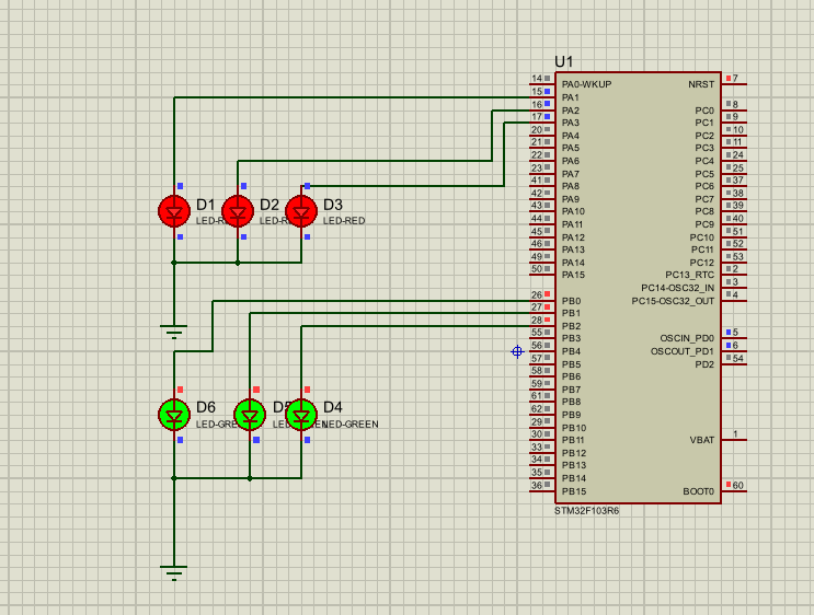
本文展示了一个基于STM32F1和FreeRTOS的双LED控制程序。主要内容包括:
-
系统配置:使用HSI时钟源通过PLL倍频至64MHz,配置系统时钟和外设时钟
-
GPIO初始化:设置PA1-PA3为红色LED输出,PB0-PB2为绿色LED输出
-
FreeRTOS任务创建:
- TaskRedLED:以400ms周期切换红色LED组
- TaskGreenLED:以1000ms周期切换绿色LED组
-
辅助功能:
- 系统时钟配置
- 错误处理函数
- 数字转换工具函数
程序采用FreeRTOS实时操作系统管理两个独立LED控制任务,实现不同频率的LED闪烁效果,展示了基本的RTOS任务创建和调度方法。
main.c
/**
  ******************************************************************************
  * File Name          : main.c
  * Description        : Dual LED Toggle with FreeRTOS (native API)
  ******************************************************************************
  */
/* Includes ------------------------------------------------------------------*/
#include "stm32f1xx_hal.h"
#include "FreeRTOS.h"
#include "task.h"

/* Peripheral handles (required by other modules for linker resolution) */
DMA_HandleTypeDef hdma_spi1_tx;
DMA_HandleTypeDef hdma_usart1_tx;
SPI_HandleTypeDef hspi1;
UART_HandleTypeDef huart1;

/* Private function prototypes -----------------------------------------------*/
void SystemClock_Config(void);
void Error_Handler(void);
static void MX_GPIO_Init(void);
static void TaskRedLED(void *pvParameters);
static void TaskGreenLED(void *pvParameters);

int main(void)
{
    /* MCU Configuration----------------------------------------------------------*/
    HAL_Init();

    /* Configure the system clock */
    SystemClock_Config();

    /* Initialize all configured peripherals */
    MX_GPIO_Init();

    /* Create the Red LED toggle task (PA1/PA2/PA3), period = 400ms */
    xTaskCreate(TaskRedLED, "RedLED", configMINIMAL_STACK_SIZE, NULL,
                tskIDLE_PRIORITY + 1, NULL);

    /* Create the Green LED toggle task (PB0/PB1/PB2), period = 1000ms */
    xTaskCreate(TaskGreenLED, "GreenLED", configMINIMAL_STACK_SIZE, NULL,
                tskIDLE_PRIORITY + 1, NULL);

    /* Start scheduler */
    vTaskStartScheduler();

    /* We should never get here as control is now taken by the scheduler */
    while (1)
    {
    }
}

/** System Clock Configuration
  * HSI -> PLL (x16) -> 64MHz SYSCLK, HCLK=32MHz, APB1=8MHz, APB2=16MHz
  */
void SystemClock_Config(void)
{
    RCC_OscInitTypeDef RCC_OscInitStruct;
    RCC_ClkInitTypeDef RCC_ClkInitStruct;

    RCC_OscInitStruct.OscillatorType = RCC_OSCILLATORTYPE_HSI;
    RCC_OscInitStruct.HSIState = RCC_HSI_ON;
    RCC_OscInitStruct.HSICalibrationValue = 16;
    RCC_OscInitStruct.PLL.PLLState = RCC_PLL_ON;
    RCC_OscInitStruct.PLL.PLLSource = RCC_PLLSOURCE_HSI_DIV2;
    RCC_OscInitStruct.PLL.PLLMUL = RCC_PLL_MUL16;
    if (HAL_RCC_OscConfig(&RCC_OscInitStruct) != HAL_OK)
    {
        Error_Handler();
    }

    RCC_ClkInitStruct.ClockType = RCC_CLOCKTYPE_HCLK | RCC_CLOCKTYPE_SYSCLK
                                  | RCC_CLOCKTYPE_PCLK1 | RCC_CLOCKTYPE_PCLK2;
    RCC_ClkInitStruct.SYSCLKSource = RCC_SYSCLKSOURCE_PLLCLK;
    RCC_ClkInitStruct.AHBCLKDivider = RCC_SYSCLK_DIV2;
    RCC_ClkInitStruct.APB1CLKDivider = RCC_HCLK_DIV4;
    RCC_ClkInitStruct.APB2CLKDivider = RCC_HCLK_DIV2;
    if (HAL_RCC_ClockConfig(&RCC_ClkInitStruct, FLASH_LATENCY_0) != HAL_OK)
    {
        Error_Handler();
    }

    HAL_SYSTICK_Config(HAL_RCC_GetHCLKFreq() / 1000);
    HAL_SYSTICK_CLKSourceConfig(SYSTICK_CLKSOURCE_HCLK);

    /* SysTick_IRQn interrupt configuration */
    HAL_NVIC_SetPriority(SysTick_IRQn, 15, 0);
}

/** Configure GPIO pins for LED control
  * PA1/PA2/PA3 -> Red LED (Output Push-Pull)
  * PB0/PB1/PB2 -> Green LED (Output Push-Pull)
  */
static void MX_GPIO_Init(void)
{
    GPIO_InitTypeDef GPIO_InitStruct;

    /* GPIO Ports Clock Enable */
    __HAL_RCC_GPIOA_CLK_ENABLE();
    __HAL_RCC_GPIOB_CLK_ENABLE();

    /* Configure PA1, PA2, PA3 as output push-pull for Red LED */
    GPIO_InitStruct.Pin = GPIO_PIN_1 | GPIO_PIN_2 | GPIO_PIN_3;
    GPIO_InitStruct.Mode = GPIO_MODE_OUTPUT_PP;
    GPIO_InitStruct.Pull = GPIO_NOPULL;
    GPIO_InitStruct.Speed = GPIO_SPEED_FREQ_LOW;
    HAL_GPIO_Init(GPIOA, &GPIO_InitStruct);

    /* Configure PB0, PB1, PB2 as output push-pull for Green LED */
    GPIO_InitStruct.Pin = GPIO_PIN_0 | GPIO_PIN_1 | GPIO_PIN_2;
    GPIO_InitStruct.Mode = GPIO_MODE_OUTPUT_PP;
    GPIO_InitStruct.Pull = GPIO_NOPULL;
    GPIO_InitStruct.Speed = GPIO_SPEED_FREQ_LOW;
    HAL_GPIO_Init(GPIOB, &GPIO_InitStruct);

    /* Set initial output level low (LEDs off) */
    HAL_GPIO_WritePin(GPIOA, GPIO_PIN_1 | GPIO_PIN_2 | GPIO_PIN_3, GPIO_PIN_RESET);
    HAL_GPIO_WritePin(GPIOB, GPIO_PIN_0 | GPIO_PIN_1 | GPIO_PIN_2, GPIO_PIN_RESET);
}

/* TaskRedLED: Toggle Red LED on PA1/PA2/PA3, period = 400ms */
static void TaskRedLED(void *pvParameters)
{
    for(;;)
    {
        HAL_GPIO_TogglePin(GPIOA, GPIO_PIN_1 | GPIO_PIN_2 | GPIO_PIN_3);
        vTaskDelay(pdMS_TO_TICKS(200));
    }
}

/* TaskGreenLED: Toggle Green LED on PB0/PB1/PB2, period = 1000ms */
static void TaskGreenLED(void *pvParameters)
{
    for(;;)
    {
        HAL_GPIO_TogglePin(GPIOB, GPIO_PIN_0 | GPIO_PIN_1 | GPIO_PIN_2);
        vTaskDelay(pdMS_TO_TICKS(500));
    }
}

/* TIM1 Period Elapsed Callback - provides HAL time base */
void HAL_TIM_PeriodElapsedCallback(TIM_HandleTypeDef *htim)
{
    if (htim->Instance == TIM1)
    {
        HAL_IncTick();
    }
}

/* itoa: convert n to characters in s (required by SSD1306 module) */
void itoa(int n, char s[])
{
    int i, sign;

    if ((sign = n) < 0)
        n = -n;
    i = 0;
    do {
        s[i++] = n % 10 + '0';
    } while ((n /= 10) > 0);
    if (sign < 0)
        s[i++] = '-';
    s[i] = '\0';

    /* reverse the string */
    int j, k;
    char c;
    for (j = 0, k = i - 1; j < k; j++, k--) {
        c = s[j];
        s[j] = s[k];
        s[k] = c;
    }
}

/**
  * @brief  This function is executed in case of error occurrence.
  */
void Error_Handler(void)
{
    while(1)
    {
    }
}

#ifdef USE_FULL_ASSERT

/**
  * @brief Reports the name of the source file and the source line number
  *   where the assert_param error has occurred.
  */
void assert_failed(uint8_t* file, uint32_t line)
{
    /* User can add his own implementation to report the file name and line number,
      ex: printf("Wrong parameters value: file %s on line %d\r\n", file, line) */
}

#endif

/************************ (C) COPYRIGHT STMicroelectronics *****END OF FILE****/

智能硬件社区聚焦AI智能硬件技术生态,汇聚嵌入式AI、物联网硬件开发者,打造交流分享平台,同步全国赛事资讯、开展 OPC 核心人才招募,助力技术落地与开发者成长。
更多推荐

 1
1 0
0- 0


 已为社区贡献1条内容

所有评论(0)