霍尔传感器角锁相环 (PLL) 滤波简谈
目录
一、锁相环 (PLL) 概述
1.1 锁相环 (PLL) 概述
详见我之前这篇文章:
二、霍尔传感器角度的锁相环 (PLL) 滤波
2.1 为什么霍尔计算的角度需要滤波
在无刷电机 (BLDC/PMSM) 控制中,三个霍尔传感器以其极低的成本提供了基本的位置反馈。然而,霍尔传感器固有的离散性 (每电周期仅提供 6 个换向点) 要求必须通过算法来拟合出连续平滑的电角度。
在实际生产中,霍尔本身的非理想切换,如:
- 霍尔传感器的安装可能存在偏差,无法保证严格 120°/60° 空间分布对称
- 组合逻辑毛刺:如 011 → 001 → 101 切换中 001 是非法状态,虽然仅持几 ns
- PWM ISR 读了一半新状态 + 一半旧状态
- 电磁干扰产生的毛刺,地参考漂移,霍尔线串扰等
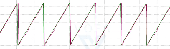
比如在下图的霍尔计算的角度下,我们可以看到其并不是平滑的,是带有毛刺的。
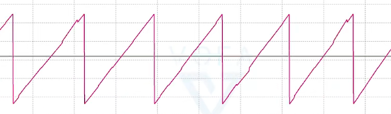
本文将深入探讨在此种非理想工况下,锁相环 (PLL) 拟合算法的基本原理概述。
2.2 使用速度计算角度
角度 = 对转速的时间积分
= 角度
- ω = 电角速度
在下面代码中形参 theta_acc_q15 是我们的当前速度,这个是根据 hall 速度计算得到的。
/**
 * @param pll             角度pll角度结构体
 * @param hall_theta_q15  霍尔计算角度
 * @param theta_acc_q15   当前速度
 */
void angle_pll_update(angle_pll_t *pll, int16_t hall_theta_q15, int16_t theta_acc_q15)
{
  /* 使用速度计算角度 */
  test_theta += theta_acc_q15;
}
2.3 鉴相器
鉴相器 (Phase Detector,PD):用来比较两个相位,并输出相位误差的模块。也就是输入两个相位,输出一个与相位差成比例的信号。
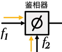
在这里鉴相器的 f1 是霍尔计算的角度,也就是下面的变量形参 hall_theta_q15
f2 则是使用我们用 PLL 估算的角度,也就是 pll->theta
/**
 * @param pll             角度pll角度结构体
 * @param hall_theta_q15  霍尔计算角度
 * @param theta_acc_q15   当前速度
 */
void angle_pll_update(angle_pll_t *pll, int16_t hall_theta_q15, int16_t theta_acc_q15)
{
  /* 鉴相器 角度误差 = 霍尔角 - 估算角 */
  pll->err = angle_diff_q15(hall_theta_q15, pll->theta);
}
2.4 环路滤波器
由于鉴相器输出的误差是不连续的,通过低通滤波器即可过滤成平滑的值供压控振荡器使用。
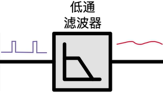
在这里我们使用一个 增量式 PID (去掉 D) 对 error 进行滤波。
可以看我之前的笔记有增量式 PID 推导:
简单来说,我们通过:
pll->err = angle_diff_q15(hall_theta_q15, pll->theta); // 鉴相器
int32_t out = (int32_t)(pll->err - pll->err_old) * pll->kp + (int32_t)(pll->err) * pll->ki; // 低通滤波器
pll->err_old = pll->err;
这两行代码实现一个低通滤波器,其 PID 的 ref 就是 hall_theta_q15 这是测量出来的带毛刺的角度。
| PID 术语 | 对应代码变量 | 含义 |
|---|---|---|
| 参考值 ref | hall_theta_q15 | 霍尔测量的实际角度 (带有毛刺的角度) |
| 测量值 meas | pll->theta | PLL 内部角度预测 |
| 误差 err | pll->err | hall_theta_q15 - pll->theta |
| PID 输出 | out | ΔErr 型 PI 输出修正量 |
| 控制量 | pll->err_int >> 15 | 积分到角度,用于修正 pll->theta |
也就是说,将霍尔测量的实际角度 (带有毛刺的角度) 设为目标值,减去上次预测出来的 pll 估算的角度,之后输出新的 pll 估算角度。
在这里的 PI 实际上被做一个低通滤波器使用。
我们可以假设 hall_theta_q15 没有毛刺,这样我们的 err 将会始终为 0。
详细代码如下:
/**
 * @param pll             角度pll角度结构体
 * @param hall_theta_q15  霍尔计算角度
 * @param theta_acc_q15   当前速度
 */
void angle_pll_update(angle_pll_t *pll, int16_t hall_theta_q15, int16_t theta_acc_q15)
{
  /* 鉴相器 角度误差 = 霍尔角 - 估算角 */
  pll->err = angle_diff_q15(hall_theta_q15, pll->theta); // 鉴相器

  /* 低通滤波器  PI 输出(ΔErr 型 P)*/
  int32_t out = (int32_t)(pll->err - pll->err_old) * pll->kp + (int32_t)(pll->err) * pll->ki; // 低通滤波器

  pll->err_old = pll->err;

  /* 积分限幅 */
  if (out > pll->out_lim)
  {
    out = pll->out_lim;
  }
  if (out < -pll->out_lim)
  {
    out = -pll->out_lim;
  }

  /* 积分到角度修正量 */
  pll->err_int += out;
}
2.5 压控振荡器
压控振荡器 (VCO,Voltage-Controlled Oscillator):输出频率 (或角速度) 由输入电压控制的振荡器。也就是输入电压,输出频率。
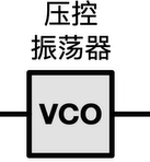
在下面是把我们用速度得到的角度和误差累加相加得到:
/**
 * @param pll             角度pll角度结构体
 * @param hall_theta_q15  霍尔计算角度
 * @param theta_acc_q15   当前速度
 */
void angle_pll_update(angle_pll_t *pll, int16_t hall_theta_q15, int16_t theta_acc_q15)
{
  /* 压控振荡器 角度更新:预测 + 修正 */
  pll->theta += theta_acc_q15 + (int16_t)(pll->err_int >> 15);
}
2.6 完整代码示例
至此,我们实现了一个完整的锁相环 (PLL) 滤波的功能:
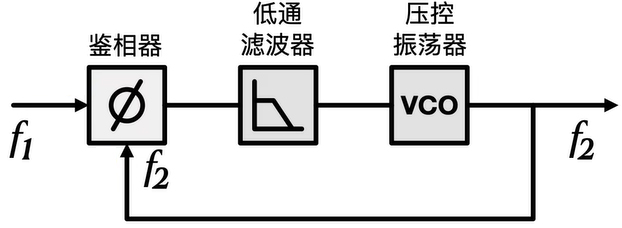
代码演示如下:
/**
 * @param pll             角度pll角度结构体
 * @param hall_theta_q15  霍尔计算角度
 * @param theta_acc_q15   当前速度
 */
void angle_pll_update(angle_pll_t *pll, int16_t hall_theta_q15, int16_t theta_acc_q15)
{
  /* 鉴相器 角度误差 = 霍尔角 - 估算角 */
  pll->err = angle_diff_q15(hall_theta_q15, pll->theta); // 鉴相器

  /* 低通滤波器  PI 输出(ΔErr 型 P)*/
  int32_t out = (int32_t)(pll->err - pll->err_old) * pll->kp + (int32_t)(pll->err) * pll->ki; // 低通滤波器

  pll->err_old = pll->err;

  /* 积分限幅 */
  if (out > pll->out_lim)
  {
    out = pll->out_lim;
  }
  if (out < -pll->out_lim)
  {
    out = -pll->out_lim;
  }

  /* 积分到角度修正量 */
  pll->err_int += out;

  /* 压控振荡器 角度更新:预测 + 修正 */
  pll->theta += theta_acc_q15 + (int16_t)(pll->err_int >> 15);
}
使用锁相环 (PLL) 波形与原始计算的波形对比:

智能硬件社区聚焦AI智能硬件技术生态,汇聚嵌入式AI、物联网硬件开发者,打造交流分享平台,同步全国赛事资讯、开展 OPC 核心人才招募,助力技术落地与开发者成长。
更多推荐

 16
16 0
0- 0


 已为社区贡献1条内容

所有评论(0)